Home/
Registry/
Ford/
Bronco/
1980-1986/
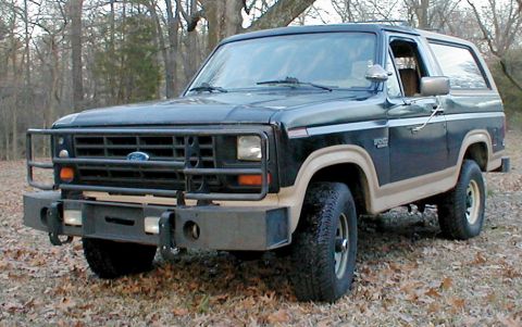
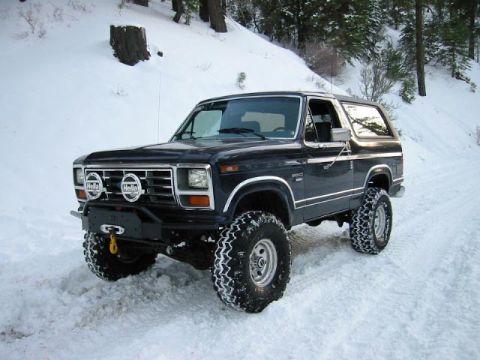
1982 Ford Bronco/
Photo
supermotors.net/registry/media/818128
Ford Bronco Body Side Trim Panel Diagram - Exploded Parts & Fasteners 831136

Reference · 1980-1986 BroncoAll 61 exploded parts diagrams
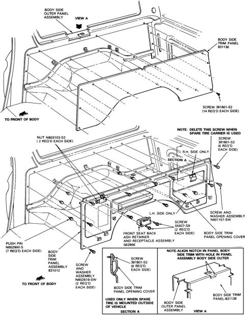

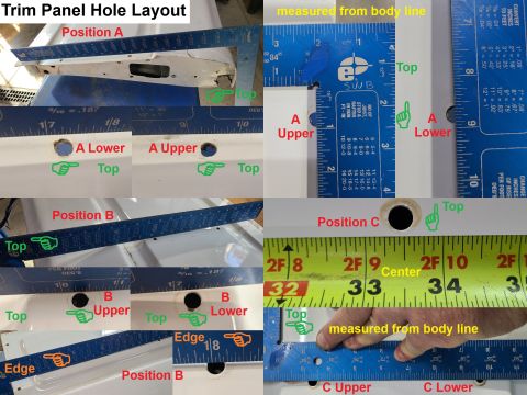
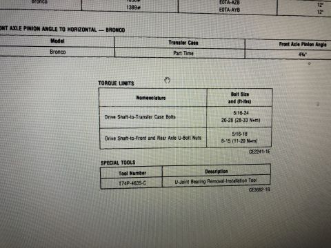
Exploded parts diagram of the body side trim panel assembly showing screws, nuts, push pins and part numbers.
Part of 1980-1986 Ford Bronco Exploded Parts Diagrams
This document is an exploded parts and installation diagram for the interior body side (bedside) trim panels of a Ford Bronco cargo area. Two main views show how the body side trim panel (part 831136) and body side trim panel assembly (831012) attach to the body side outer panel assembly. Fasteners are called out with part numbers and quantities: screw 381801-S2 (14 required each side for the upper panel; 6 required each side for the opening cover), nut N803103-S2 (2 per side), push pin N802900-S (7 per side), screw 55927-S9 (2 per side), screw and washer assemblies N801157-SW and N802619-SW (2 per side). The front seat back ash retainer and receptacle assembly (562866) is also shown. Notes indicate one screw must be deleted when a spare tire carrier is used, that certain covers apply to R.H. or L.H. sides only, and that the body side trim panel opening cover is used only when the spare tire is mounted outside the vehicle (Section A inset). View A inset shows aligning the notch in the trim panel with the hole in the outer body panel. Useful for anyone removing or reinstalling Bronco rear interior quarter trim panels.
Is this accurate? Sign in to help verify it.
Frequently asked questions
- How many screws hold the body side trim panel 831136 on each side?
- Screw 381801-S2 is used, with 14 required each side for the body side trim panel.
- How many push pins are used per side on the body side trim panel assembly?
- Push pin N802900-S is used, 7 required each side.
- When is the body side trim panel opening cover used?
- Per Section A, it is used only when the spare tire is mounted outside of the vehicle, secured with screw 381801-S2 (6 required each side).
- What should be done with the screw location when a spare tire carrier is used?
- The note states to delete this screw when the spare tire carrier is used (R.H. side only location shown).
- What alignment is required when installing the body side trim panel?
- View A notes to align the notch in the body side trim panel with the hole in the body side outer panel assembly.
No comments yet.