Home/
Registry/
Ford/
Bronco/
1992-1996/
“pukin' dogII”/
Photo
supermotors.net/registry/media/877800
1996 Ford Bronco DRL Wiring Diagram - Daytime Running Lamps Circuit

Reference · 1992-1996 BroncoAll 411 wiring diagrams
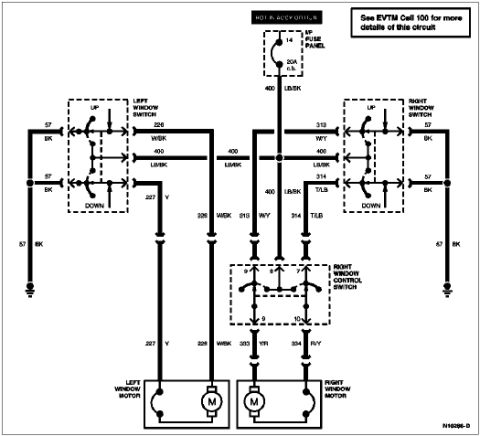
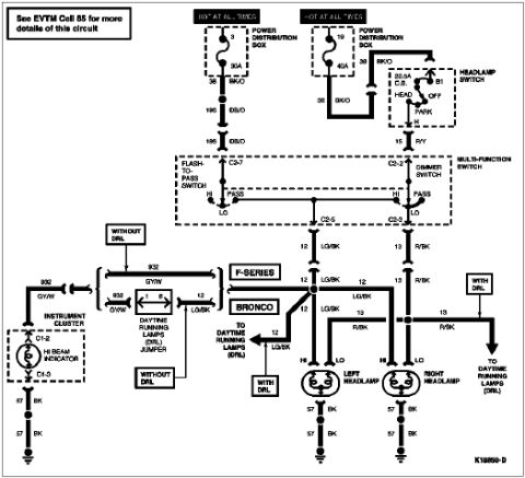
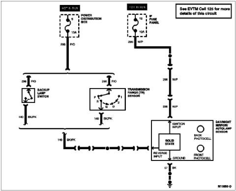
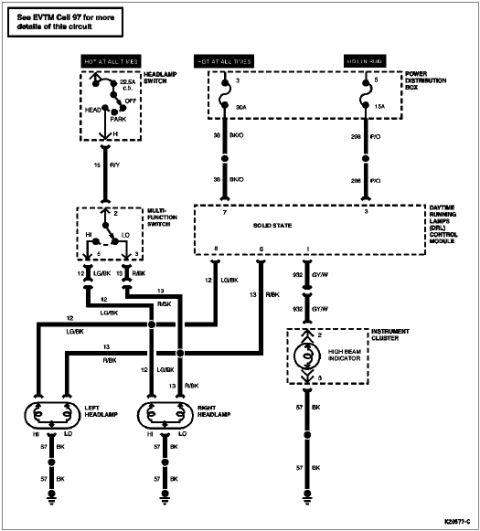













Electrical wiring diagram of the headlamp and DRL circuit with headlamp switch, DRL module and color-coded wires.
Part of 1992-1996 Ford Bronco Wiring Diagrams
This document is a wiring diagram for the Daytime Running Lamps (DRL) system, uploaded for a 1996 Ford Bronco. It shows power flowing from two sources: a Hot At All Times circuit through a 30A fuse in the Power Distribution Box (circuit 38/36 BK/O to pin 7 of the DRL module) and a Hot In Run circuit through a 15A fuse (circuit 298/296 P/O to pin 3). The headlamp switch, protected by an internal 22.5A circuit breaker and hot at all times, feeds circuit 15 R/Y to pin 2 of the multi-function switch, which selects HI (pin 5, circuit 12 LG/BK) or LO (pin 3, circuit 13 R/BK) beams. The solid-state DRL control module outputs on pins 8 (12 LG/BK) and 6 (13 R/BK) to the left and right headlamps, each grounded through circuit 57 BK. Module pin 1 drives circuit 932 GY/W to the high beam indicator in the instrument cluster (pins 2 and 3), which grounds through 57 BK. A note refers readers to EVTM Cell 97 for more circuit details. Diagram reference number K20577-C appears in the corner.
Is this accurate? Sign in to help verify it.
Frequently asked questions
- What fuses power the DRL system in this diagram?
- The Power Distribution Box supplies a 30A fuse on a Hot At All Times circuit (38/36 BK/O to module pin 7) and a 15A fuse on a Hot In Run circuit (298/296 P/O to module pin 3). The headlamp switch also has a 22.5A circuit breaker.
- What wire colors go to the headlamps?
- Circuit 12 LG/BK (light green/black) feeds the high beams and circuit 13 R/BK (red/black) feeds the low beams on both headlamps; ground is circuit 57 BK (black).
- What wire operates the high beam indicator?
- Circuit 932 GY/W (gray/white) runs from pin 1 of the DRL control module to the high beam indicator in the instrument cluster (pins 2 and 3), which grounds through 57 BK.
- Where can I find more details on this circuit?
- The diagram notes: 'See EVTM Cell 97 for more details of this circuit.'
- Which multi-function switch pins select high and low beams?
- Input is pin 2 (circuit 15 R/Y from the headlamp switch); HI output is pin 5 (12 LG/BK) and LO output is pin 3 (13 R/BK).






No comments yet.