Home/
Registry/
Ford/
Bronco/
1992-1996/
“pukin' dogII”/
Photo
supermotors.net/registry/media/877803
1996 Ford Bronco Electronic Day/Night Mirror & Autolamp Wiring Diagram

Reference · 1992-1996 BroncoAll 411 wiring diagrams
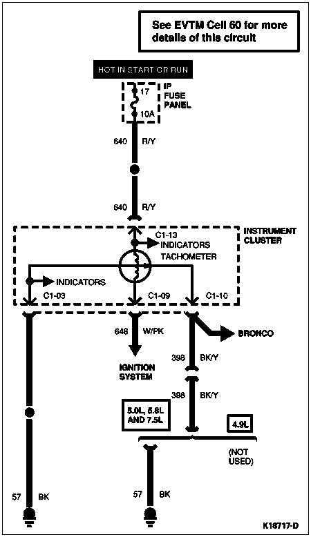
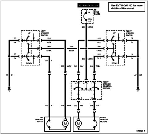
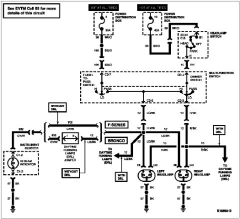
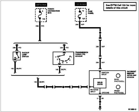
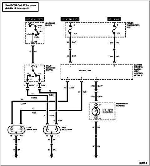
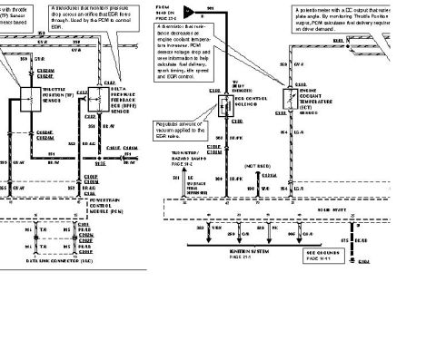
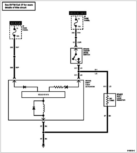
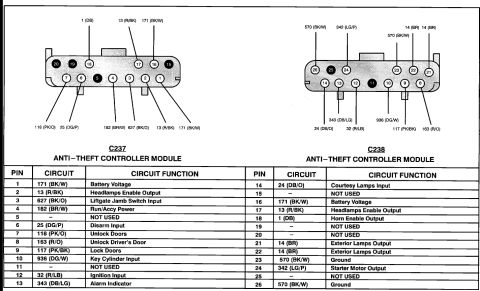













Electrical wiring diagram of the backup lamp, transmission range sensor and day/night autolamp circuit with color codes.
Part of 1992-1996 Ford Bronco Wiring Diagrams
This document is a wiring diagram for the electronic day/night mirror with autolamp sensor, filed for a 1996 Ford Bronco. It shows two power feeds, both hot in run: circuit 298 (P/O, pink/orange) from Power Distribution Box fuse 5 (15A) and circuit 296 (W/P, white/purple) from Fuse Panel fuse 13 (10A). Circuit 296 W/P feeds the ignition input of the day/night mirror/autolamp sensor module. Circuit 298 P/O feeds two alternative reverse-signal sources: the backup lamp switch (manual transmission) and the transmission range (TR) sensor (automatic transmission, showing gear positions P, R, N, D, 2, 1); either switch outputs on circuit 140 (BK/PK, black/pink) to the reverse input of the mirror module. The module is shown as a solid-state device with a back photocell and a front photocell, and it grounds through circuit 57 (BK, black). A callout notes to see EVTM Cell 125 for more details of this circuit. Diagram reference number IN10958-D appears at the bottom. A reader can learn the fuse locations/amperages, circuit numbers, wire colors, and signal paths needed to diagnose the auto-dimming mirror or autolamp system.
Is this accurate? Sign in to help verify it.
Frequently asked questions
- Which fuses power the day/night mirror/autolamp sensor circuit?
- Two hot-in-run feeds: fuse 5 (15A) in the Power Distribution Box on circuit 298 P/O, and fuse 13 (10A) in the fuse panel on circuit 296 W/P.
- What wire feeds the ignition input of the day/night mirror module?
- Circuit 296, white with purple stripe (W/P), from fuse panel fuse 13 (10A, hot in run).
- Where does the mirror's reverse input signal come from?
- Circuit 140 BK/PK, which comes from either the backup lamp switch or the transmission range (TR) sensor, both fed by circuit 298 P/O from Power Distribution Box fuse 5 (15A).
- How is the day/night mirror grounded?
- The ground terminal of the module goes to ground through circuit 57, black (BK).
- What photocells does the day/night mirror/autolamp sensor contain?
- The diagram shows a back photocell and a front photocell in the solid-state day/night mirror/autolamp sensor module.






No comments yet.