Home/
Registry/
Ford/
Bronco/
1992-1996/
“pukin' dogII”/
Photo
supermotors.net/registry/media/877823
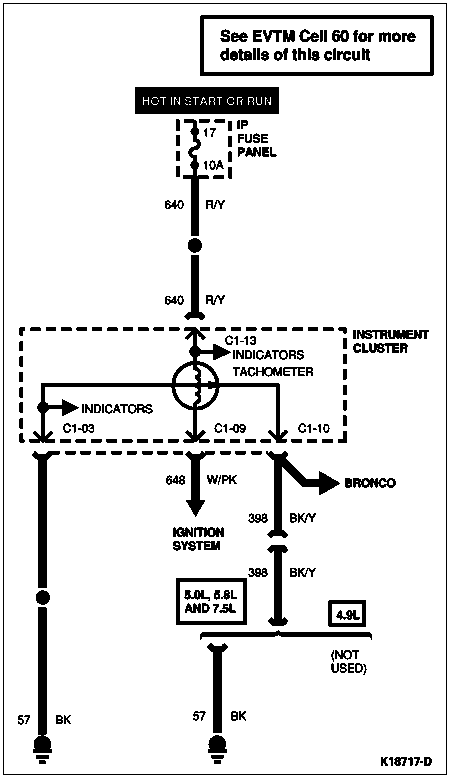
1996 Ford Bronco Tachometer Wiring Diagram - Instrument Cluster Circuit
Reference · 1992-1996 BroncoAll 411 wiring diagrams
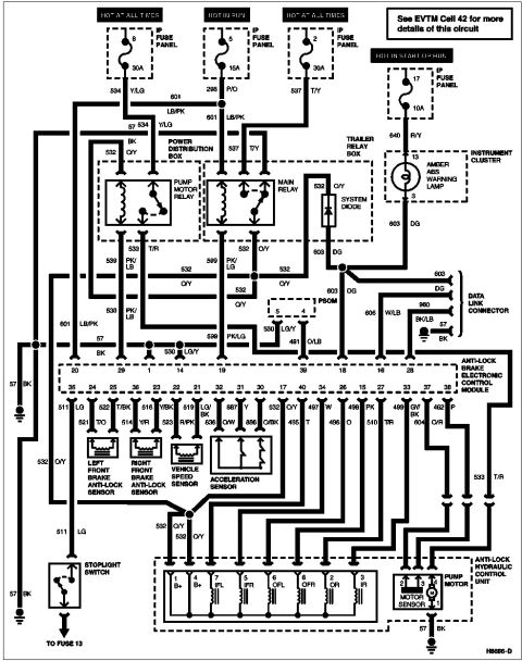
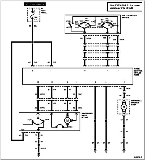
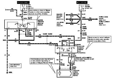
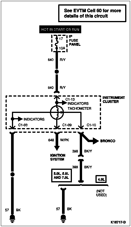
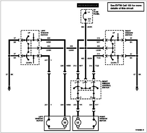
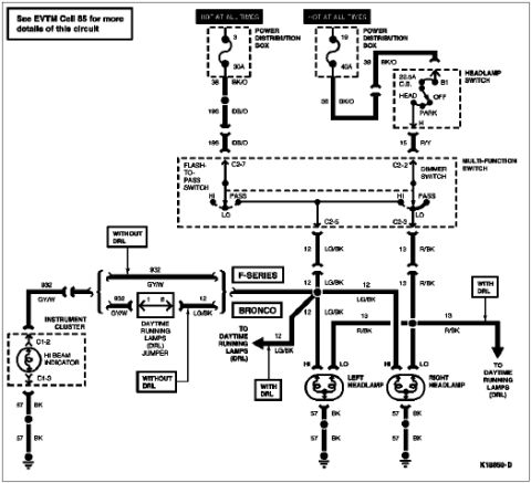
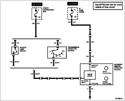
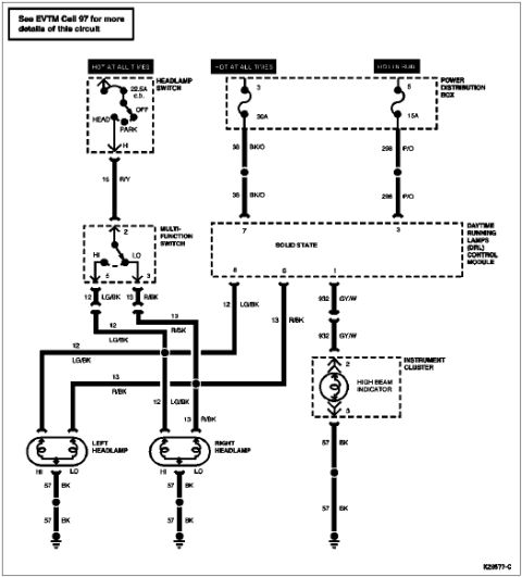

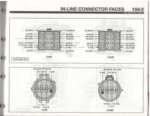
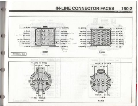
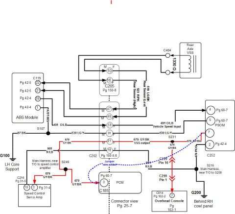
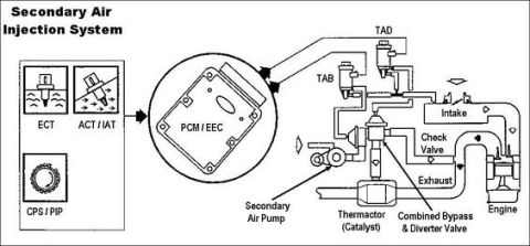
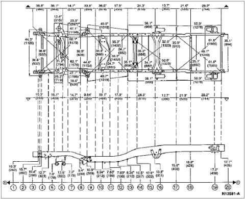
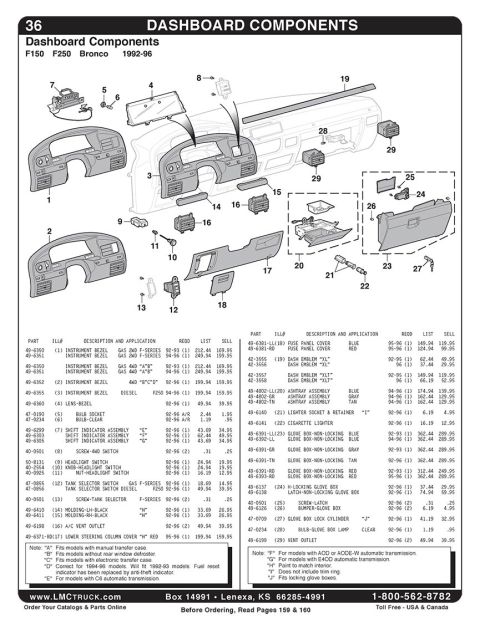
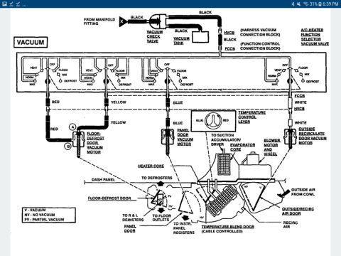

Wiring diagram of the tachometer/ignition-system circuit showing the instrument cluster, fuse panel and engine-specific wiring.
Part of 1992-1996 Ford Bronco Wiring Diagrams
This is a factory-style wiring diagram (schematic ID K18717-D) showing the tachometer circuit within the instrument cluster, with a note referring to EVTM Cell 60 for more circuit details. Power is supplied from IP fuse panel fuse 17 (10A), which is hot in START or RUN, through circuit 640 (red/yellow wire) to the instrument cluster. Inside the cluster, the tachometer connects to indicators via connector pins C1-13 and other branches. Connector C1-09 carries circuit 648 (white/pink) to the ignition system. Connector C1-10 branches to the Bronco via circuit 398 (black/yellow), which continues through a splice; this path applies to 5.0L, 5.8L and 7.5L engines, and is marked NOT USED for the 4.9L engine. Grounding is provided through circuit 57 (black wires) from connector C1-03 and from the 398 circuit path, each terminating at chassis ground. A reader can learn the fuse feeding the tachometer, the wire circuit numbers and color codes (640 R/Y, 648 W/PK, 398 BK/Y, 57 BK), the instrument cluster connector pin identifiers (C1-03, C1-09, C1-10, C1-13), and engine-specific applicability of the 398 circuit.
Is this accurate? Sign in to help verify it.
Frequently asked questions
- Which fuse powers the tachometer circuit in this diagram?
- Fuse 17, a 10A fuse in the IP fuse panel, which is hot in START or RUN.
- What wire color and circuit number feed power to the instrument cluster tachometer?
- Circuit 640, a red/yellow (R/Y) wire, runs from fuse 17 to the instrument cluster.
- What circuit connects the tachometer to the ignition system?
- Circuit 648, a white/pink (W/PK) wire, from instrument cluster connector C1-09 to the ignition system.
- Which engines use the 398 BK/Y circuit?
- The 5.0L, 5.8L and 7.5L engines use circuit 398 (black/yellow); it is marked NOT USED for the 4.9L.
- Where do I find more details on this tachometer circuit?
- The diagram directs you to EVTM Cell 60 for more details of this circuit.






No comments yet.