Home/
Registry/
Ford/
Bronco/
1992-1996/
“pukin' dogII”/
Photo
supermotors.net/registry/media/877852
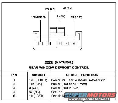
1996 Ford Bronco Rear Window Defrost Control C279 Connector Pinout Diagram
Reference · 1992-1996 BroncoAll 411 wiring diagrams
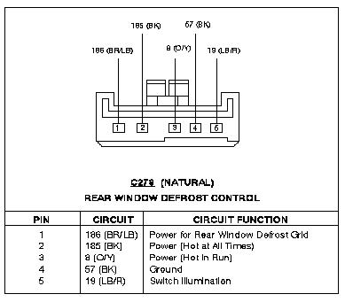
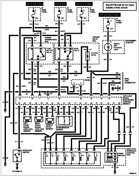
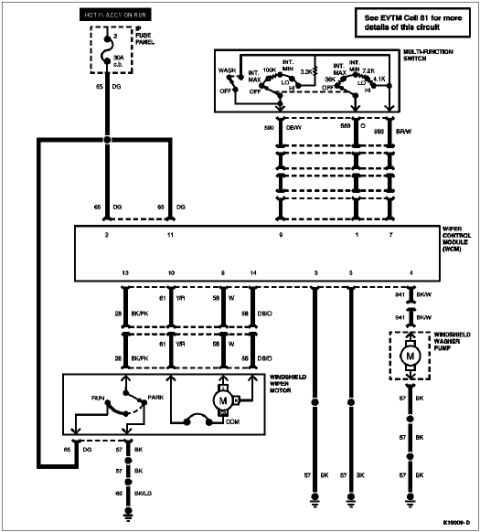
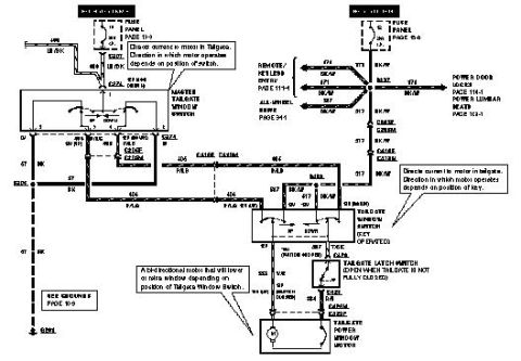
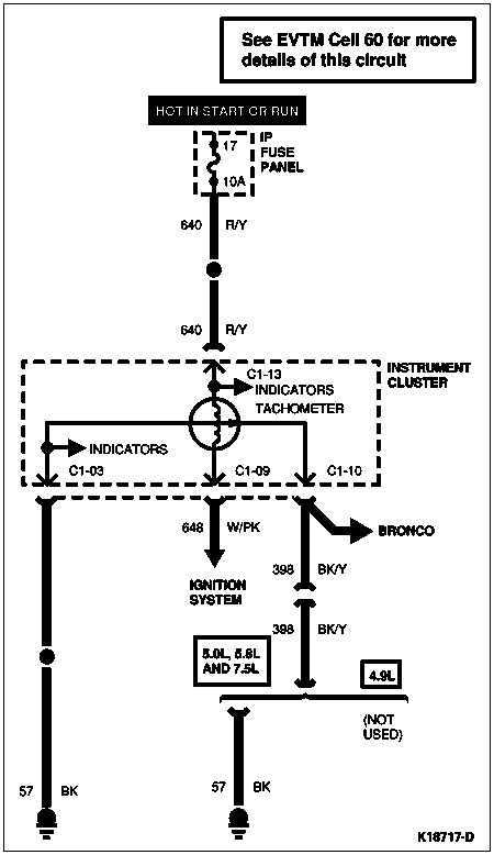













Wiring connector pinout for the rear window defrost control (C279) listing pin numbers, wire colors and circuit functions.
Part of 1992-1996 Ford Bronco Wiring Diagrams
This document is a connector pinout diagram for connector C279 (natural color), the Rear Window Defrost Control connector, filed by the uploader for a 1996 Ford Bronco. The top portion shows a face view of the 5-pin connector with circuit numbers and wire colors called out for each cavity: circuit 186 (brown/light blue), 185 (black), 8 (orange/yellow), 57 (black), and 19 (light blue/red). Below the drawing, a table lists each pin, its circuit number and wire color, and the circuit function: Pin 1 is circuit 186 (BR/LB), power for the rear window defrost grid; Pin 2 is circuit 185 (BK), power hot at all times; Pin 3 is circuit 8 (O/Y), power hot in run; Pin 4 is circuit 57 (BK), ground; and Pin 5 is circuit 19 (LB/R), switch illumination. A reader can use this diagram to identify wires at the rear window defroster control switch, verify power, ground, and illumination circuits, and troubleshoot a non-working rear defrost grid or switch backlight. The document itself carries no printed year or model designation.
Is this accurate? Sign in to help verify it.
Frequently asked questions
- What is connector C279 on the rear window defrost control?
- C279 is the natural-colored 5-pin connector for the Rear Window Defrost Control, with pins 1-5 carrying circuits 186, 185, 8, 57, and 19.
- Which pin powers the rear window defrost grid?
- Pin 1, circuit 186 with a brown/light blue (BR/LB) wire, provides power for the Rear Window Defrost Grid.
- Which wire is hot at all times at the defrost control connector?
- Pin 2, circuit 185 with a black (BK) wire, is power that is hot at all times.
- Where is the ground on the rear defrost control connector?
- Pin 4, circuit 57 with a black (BK) wire, is the ground.
- What circuit provides the defrost switch illumination?
- Pin 5, circuit 19 with a light blue/red (LB/R) wire, provides switch illumination.






No comments yet.