Home/
Registry/
Ford/
Bronco/
1992-1996/
“pukin' dogII”/
Photo
supermotors.net/registry/media/877853
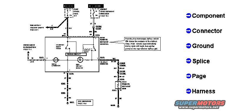
1996 Ford Bronco Rear Window Defroster Wiring Diagram - Defrost Circuit
Reference · 1992-1996 BroncoAll 411 wiring diagrams
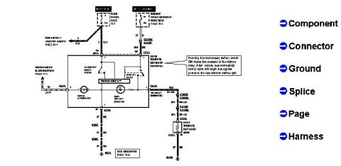













Rear window defrost wiring diagram showing fuse/power distribution box, defrost switch, indicator, relay and grid, with a legend defining component, connector, ground, splice, page and harness symbols.
Part of 1992-1996 Ford Bronco Wiring Diagrams
This is a wiring diagram for the rear window defrost (defroster) system, uploaded for a 1996 Ford Bronco. The diagram shows power feeds from two sources: the interior fuse panel (referenced to page 13-1) and the engine compartment fuse box (referenced to page 13-4). Power routes through a rear window defrost control module containing a momentary on/off switch, a timing circuit, and switch illumination (tied to instrument illumination, page 71-1). A callout note explains the operation: pressing the momentary defrost switch ON closes the contacts of the defrost relay, and a timing cycle (approximately ten minutes) then applies power to the rear window defrost grid. The circuit continues through several connectors and splices on the right side of the diagram to the rear window defrost grid element, which grounds at the rear of the vehicle. Multiple black (BK) ground wires from the control module lead to chassis grounds, with a reference to "See Grounds, page 10-9." A legend on the right identifies diagram symbols for Component, Connector, Ground, Splice, Page, and Harness. Due to the very low scan resolution, most connector numbers, circuit numbers, and wire color codes are only partially legible.
Is this accurate? Sign in to help verify it.
Frequently asked questions
- How does the rear window defroster switch work on this circuit?
- Per the diagram's callout, pressing the momentary defrost switch ON closes the contacts of the defrost relay; a timing cycle (approximately ten minutes) then begins that applies power to the rear window defrost grid.
- Where does the rear defrost circuit get its power?
- From two sources shown at the top of the diagram: the fuse panel (see page 13-1) and the engine compartment fuse box (see page 13-4).
- What does the rear window defrost control module contain?
- The control block shown includes a momentary on/off switch, a timing circuit, and switch illumination tied to the instrument illumination circuit (page 71-1).
- Where can I find the ground locations for this circuit?
- The diagram notes 'See Grounds, page 10-9' for the black (BK) ground wires from the defrost control.






No comments yet.