MegaSquirt II Power Supply & CPU Clock Schematic with Voltage Test Readings
Reference · 1993-1997 ProbeAll 25 schematics
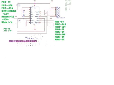
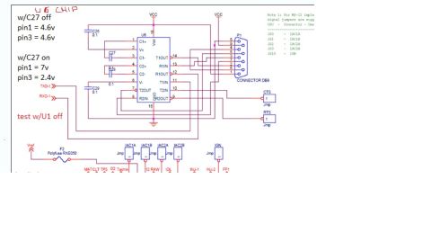
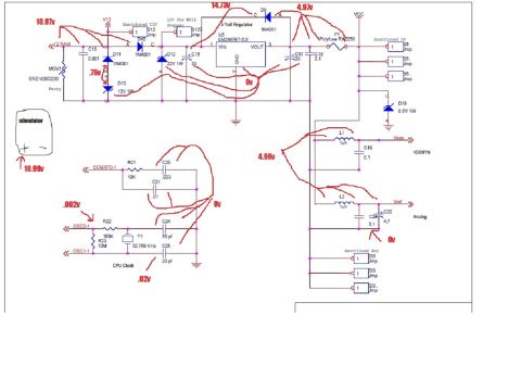
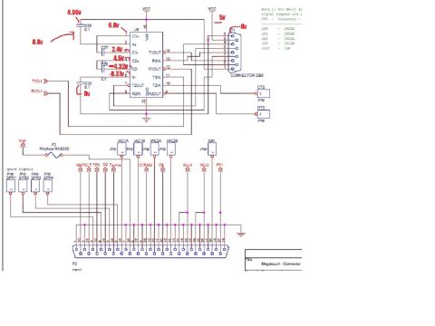
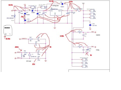
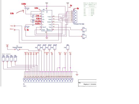










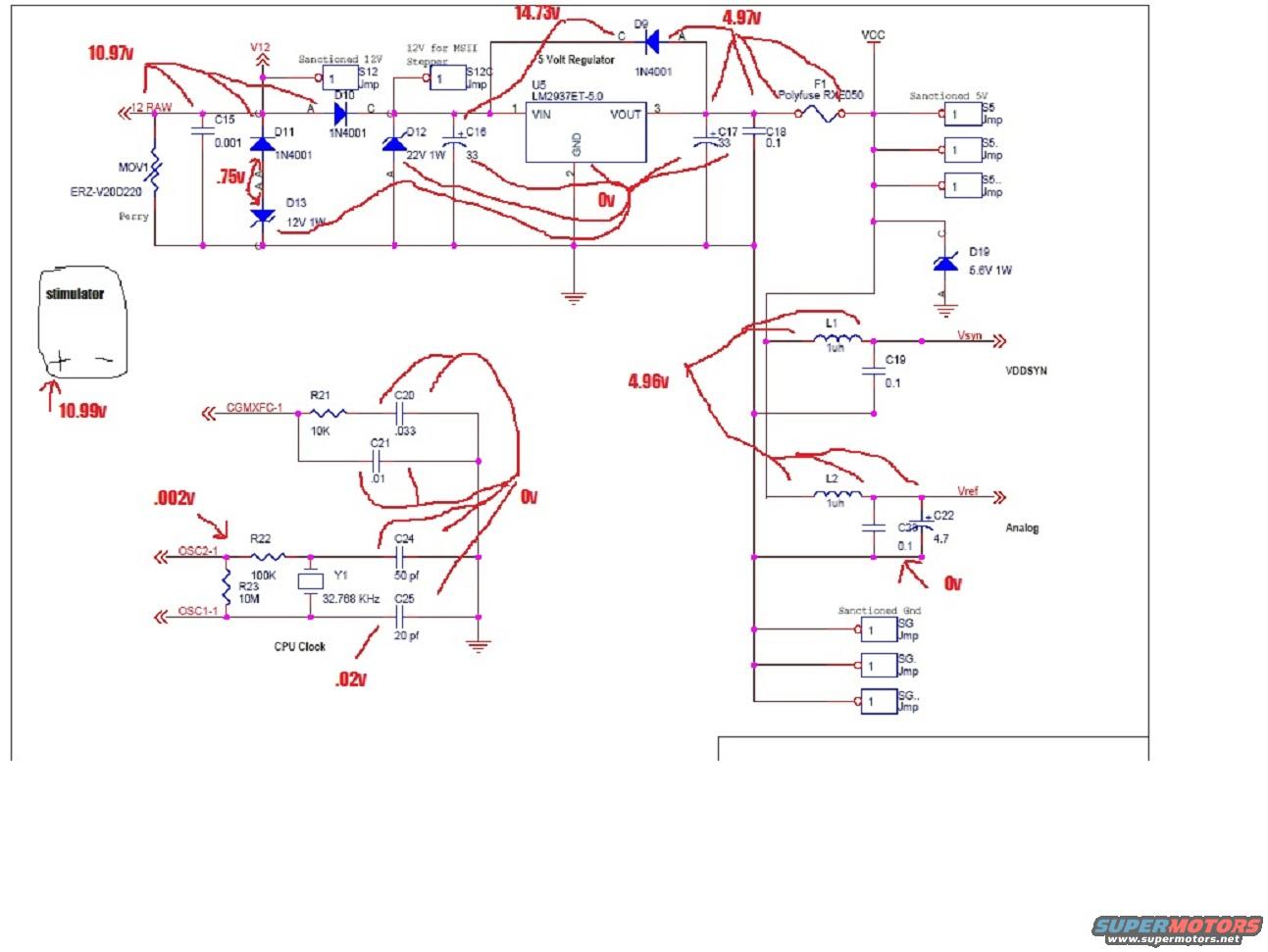
Megasquirt power-supply schematic annotated with measured voltages across the voltage regulator, supply rails and CPU clock crystal.
Part of 1993-1997 Ford Probe Schematics
This document is a schematic of the power supply and CPU clock sections of a MegaSquirt-II (MSII) engine management controller board, annotated by hand in red with measured voltage readings, apparently for troubleshooting. The power supply section shows a 12V RAW input protected by MOV1 (ERZ-V20D220), diodes D10/D11 (1N4001), zener diodes D12 (22V 1W) and D13 (12V 1W), feeding a 5-volt regulator U5 (LM2937ET-5.0) with filter capacitors C16/C17 (33) and C18 (0.1). Output VCC passes through polyfuse F1 (RXE050) to 'Sanctioned 5V' jumpers (S5). Inductors L1 and L2 (1uH) with capacitors C19, C22 (4.7) and C23 (0.1) filter the Vsyn/VDDSYN and Vref/Analog rails. D19 is a 5.6V 1W zener. The CPU clock section includes crystal Y1 (32.768 KHz), R22 (100K), R23 (10M), C24 (50pf), C25 (20pf), plus R21 (10K), C20 (.033) and C21 (.01) on CGMXFC-1. Handwritten measurements include 10.97v at 12 RAW, 14.73v and 4.97v around the regulator, 4.96v on the 5V rail, .75v across D13, and near-zero readings at oscillator pins, with a 'stimulator' supplying 10.99v. Useful for diagnosing MSII power/clock faults.
Is this accurate? Sign in to help verify it.
Frequently asked questions
- What voltage regulator does this MSII power supply schematic use?
- U5, an LM2937ET-5.0 5-volt regulator, with VIN on pin 1, VOUT on pin 3, and GND on pin 2.
- What crystal frequency is used for the CPU clock?
- Y1 is a 32.768 KHz crystal, with C24 (50 pf) and C25 (20 pf) load capacitors, R22 (100K) and R23 (10M).
- What voltage readings are annotated on the power supply?
- Handwritten readings include 10.97v at 12 RAW, 14.73v before D9, 4.97v after the regulator, 4.96v on the 5V rail, .75v across D13, 10.99v from the stimulator, and 0v, .002v and .02v at various points.
- What fuse protects the 5V output?
- F1, a Polyfuse RXE050, between the regulator output and the Sanctioned 5V jumpers.
- What surge protection components are on the 12V input?
- MOV1 (ERZ-V20D220), 1N4001 diodes D10 and D11, a 22V 1W zener D12, a 12V 1W zener D13, and C15 (0.001).






No comments yet.