U6 Chip Serial Interface Schematic & Test Voltages - Shorted Board Diagnosis
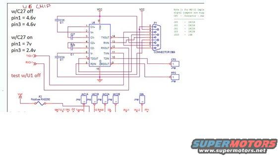
Megasquirt schematic of the U6 MAX232 area annotated with measured pin voltages for capacitor C27 on and off test conditions.
This document is a partial electronic schematic, annotated by hand, focused on the U6 chip of a circuit board (an RS-232 level converter type IC with C1+/C1-, C2+/C2-, V+, V-, T1IN/T1OUT, T2IN/T2OUT, R1IN/R1OUT, R2IN/R2OUT pins) connected to a DB9 serial connector (P1). Red handwritten test notes record diagnostic voltage measurements for troubleshooting a shorted board: with capacitor C27 off, pin 1 and pin 3 both read 4.6V; with C27 on, pin 1 reads 7V and pin 3 reads 2.4V; and a note says to test with U1 off. The schematic shows supporting capacitors C26, C27, C28, and C29 (0.1 values noted), TXD-1 and RXD-1 signal lines, and CTS/RTS jumpers. A printed note references MU-II implementation signal jumpers, listing CPU jumper designations J80–J83 and J810 mapped to IAC1A, IAC1B, IAC2A, IAC2B, and IGN. The lower portion shows a Vref line through polyfuse F2 (RXE050), jumpers for the IAC and IGN signals, and sensor/actuator labels including MAT, CLT, TPS, O2, Tachin, 12 RAW, IDL, INJ-1, INJ-2, and FP1. The image is cropped, cutting off part of the note text and lower schematic. This appears to be aftermarket ECU/serial-interface documentation rather than a factory Ford Probe diagram.
Is this accurate? Sign in to help verify it.
Frequently asked questions
- What voltages should the U6 chip pins read with C27 off?
- Per the handwritten notes, with C27 off, pin 1 = 4.6V and pin 3 = 4.6V.
- What voltages appear on U6 with C27 installed (on)?
- With C27 on, pin 1 reads 7V and pin 3 reads 2.4V.
- What jumpers correspond to the CPU jumper designations J80 through J810?
- J80 = IAC1A, J81 = IAC1B, J82 = IAC2A, J83 = IAC2B, and J810 = IGN.
- What protects the Vref line in this schematic?
- F2, a polyfuse labeled RXE050.
- What connector does the U6 chip interface with?
- P1, a DB9 connector, with TXD-1, RXD-1 signals and CTS/RTS jumper options.
Comments
More from this build




No comments yet.