Ford Probe ECU Board U6 MAX232-Type IC Pin Voltages - Good Board Reference
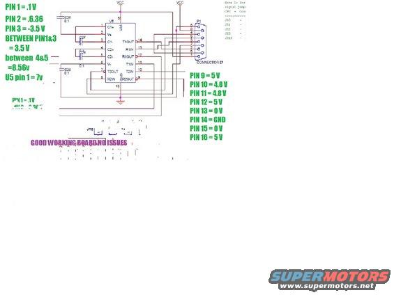
Megasquirt MAX232 serial-interface schematic annotated with known-good board pin voltages for the DB9 connector pins 1-16.
This document is an annotated electronic schematic showing a 16-pin serial line driver/receiver IC labeled U6 (with pin functions C1+, V+, C1-, C2+, C2-, V-, T2OUT, R2IN, R2OUT, T2IN, T1IN, R1OUT, R1IN, T1OUT, GND, Vdd — the classic MAX232-style pinout) connected through 0.1 µF capacitors (C26, C27, C28, C29) to a 9-pin D-sub connector labeled P1. The uploader has overlaid measured voltage readings from a known-good circuit board: Pin 1 = 0.1 V, Pin 2 = 6.36 V, Pin 3 = -3.5 V, 3.5 V between pins 1 and 3, 8.56 V between pins 4 and 5, and U5 pin 1 = 7 V. The right-side annotations list Pin 9 = 5 V, Pin 10 = 4.8 V, Pin 11 = 4.8 V, Pin 12 = 5 V, Pin 13 = 0 V, Pin 14 = GND, Pin 15 = 0 V, Pin 16 = 5 V. A large caption states 'GOOD WORKING BOARD NO ISSUES,' indicating these are reference voltages for diagnosing a faulty board (likely an ECU/cluster serial interface, per the album context). A partially legible note references signal jumpers JS0, JS1, JS2, JS3, JS10 between CPU and connector.
Is this accurate? Sign in to help verify it.
Frequently asked questions
- What are the good-board voltage readings for the U6 IC pins?
- Pin 1 = 0.1 V, Pin 2 = 6.36 V, Pin 3 = -3.5 V (3.5 V between pins 1 and 3), 8.56 V between pins 4 and 5, Pin 9 = 5 V, Pin 10 = 4.8 V, Pin 11 = 4.8 V, Pin 12 = 5 V, Pin 13 = 0 V, Pin 14 = GND, Pin 15 = 0 V, Pin 16 = 5 V. Also noted: U5 pin 1 = 7 V.
- What are the pin functions of the U6 chip in this schematic?
- Pin 1 C1+, Pin 2 V+, Pin 3 C1-, Pin 4 C2+, Pin 5 C2-, Pin 6 V-, Pin 7 T2OUT, Pin 8 R2IN, Pin 9 R2OUT, Pin 10 T2IN, Pin 11 T1IN, Pin 12 R1OUT, Pin 13 R1IN, Pin 14 T1OUT, Pin 15 GND, Pin 16 Vdd.
- What capacitors are connected to U6?
- Capacitors C26, C27, C28, and C29 are shown, with 0.1 (µF) values marked on C26, C29, and near C28.
- What does U6 connect to on this board?
- The transmit/receive lines from U6 route to a 9-pin connector labeled P1, identified as 'CONNECTOR D' (a D-sub connector) with pins 1-9 shown.
- Were these measurements taken from a working or faulty board?
- The document states 'GOOD WORKING BOARD NO ISSUES,' so the voltages are reference values from a known-good board.
Comments
More from this build




No comments yet.