MegaSquirt MS2 VR/Tach Input Circuit Schematic - 4N25 Opto & MC34072AP Debug
Reference · 1993-1997 ProbeAll 25 schematics










Annotated electronic circuit schematic showing an opto-isolator input stage and MC34072 op-amp comparators with hysteresis and zero-crossing setpoint.
Part of 1993-1997 Ford Probe Schematics
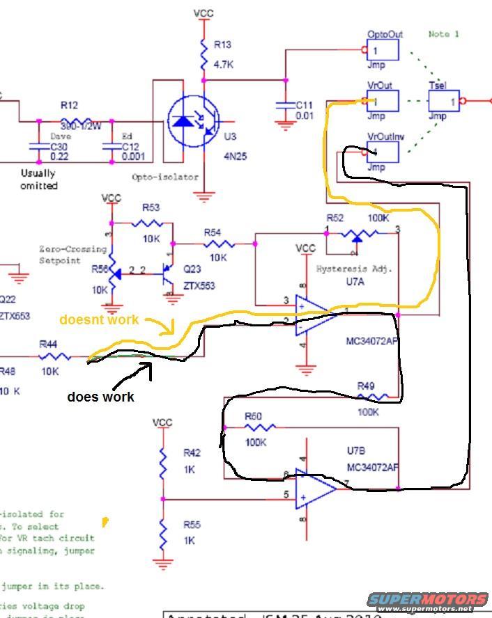
This document is an annotated electronic schematic (filename 'ms2 fail.jpg') showing a tach/ignition input-conditioning circuit, apparently from a MegaSquirt-style engine controller. It includes an opto-isolator (U3, 4N25) with input resistor R12 (390 ohm 1/2W) and capacitors labeled 'Dave C30 0.22' and 'Ed C12 0.001' (noted as 'usually omitted'), a pull-up R13 (4.7K) to VCC, and filter cap C11 (0.01). Output jumper options are shown: OptoOut, VrOut, VrOutInv, and Tsel. The VR (variable reluctor) conditioning section uses a dual op-amp MC34072AP (U7A/U7B) with a Zero-Crossing Setpoint network (R53, R56, both 10K, transistor Q23 ZTX553), a Hysteresis Adjust pot R52 (100K), and feedback/divider resistors R49 and R50 (100K), R42 and R55 (1K), plus input resistors R44 (10K) and R48 (10K). The uploader has hand-drawn two signal paths: a yellow trace labeled 'doesnt work' running from the input through the VrOut jumper to the U7A comparator input, and a black trace labeled 'does work' following an alternate routing through VrOutInv and the U7B stage. The caption indicates it was annotated by JSM on 25 Aug 2010. It documents troubleshooting of which VR conditioner signal path functions.
Is this accurate? Sign in to help verify it.
Frequently asked questions
- What opto-isolator is used in this tach input circuit?
- U3, a 4N25 opto-isolator, with a 4.7K pull-up resistor (R13) to VCC and a 0.01 filter capacitor (C11) on its output.
- What op-amp handles the VR signal conditioning?
- An MC34072AP dual op-amp, shown as U7A and U7B, with a Zero-Crossing Setpoint network (R53/R56, 10K each, Q23 ZTX553) and a 100K Hysteresis Adjust pot (R52).
- What do the yellow and black hand-drawn lines mean?
- They mark troubleshooting results: the yellow path through the VrOut jumper is labeled 'doesnt work,' while the black path (through VrOutInv and the U7B stage) is labeled 'does work.'
- What jumper output options are shown on the schematic?
- OptoOut, VrOut, VrOutInv, and Tsel jumpers, referenced to 'Note 1.'
- What input components feed the opto-isolator?
- R12 (390 ohm 1/2W) plus two optional capacitors: C30 0.22 (labeled 'Dave') and C12 0.001 (labeled 'Ed'), noted as 'usually omitted.'






No comments yet.