Home/
Registry/
Ford/
Bronco/
1978-1979/
“buyers guide”/
Photo
supermotors.net/registry/media/994558
Ford V8 Positive Stop Valve Clearance Procedure - Crankshaft Positioning Fig 170

Reference · 1978-1979 BroncoAll 48 service procedures
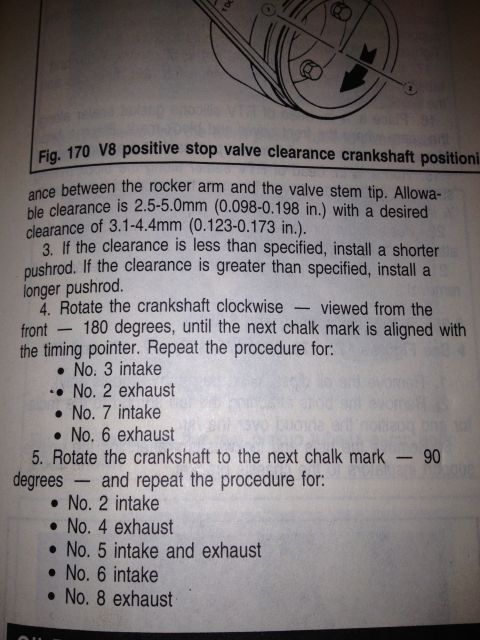
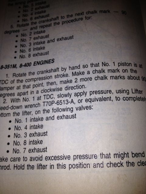
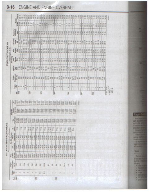
Step-by-step service procedure for V8 positive stop valve clearance, listing crankshaft rotation positions and intake/exhaust valves.
Part of 1978-1979 Ford Bronco Service Procedures
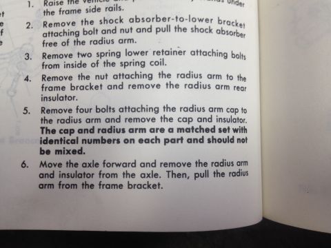
This is a scanned page from an automotive service manual covering the positive-stop rocker arm valve clearance checking procedure for a Ford V8 engine. The top of the page shows part of an illustration labeled 'Fig. 170 V8 positive stop valve clearance crankshaft positioning,' depicting crankshaft/damper rotation with numbered chalk-mark positions. The text specifies the clearance between the rocker arm and the valve stem tip: allowable clearance is 2.5-5.0mm (0.098-0.198 in.) with a desired clearance of 3.1-4.4mm (0.123-0.173 in.). Step 3 instructs that if clearance is less than specified, a shorter pushrod should be installed; if greater than specified, a longer pushrod should be installed. Step 4 directs rotating the crankshaft clockwise (viewed from the front) 180 degrees until the next chalk mark aligns with the timing pointer, then repeating the check for No. 3 intake, No. 2 exhaust, No. 7 intake, and No. 6 exhaust valves. Step 5 directs rotating the crankshaft another 90 degrees to the next chalk mark and repeating for No. 2 intake, No. 4 exhaust, No. 5 intake and exhaust, No. 6 intake, and No. 8 exhaust. This gives a reader the valve clearance specifications and the crankshaft rotation sequence for checking all valves on the V8 engine.
Is this accurate? Sign in to help verify it.
Frequently asked questions
- What is the allowable valve clearance between the rocker arm and valve stem tip on this V8?
- Allowable clearance is 2.5-5.0mm (0.098-0.198 in.), with a desired clearance of 3.1-4.4mm (0.123-0.173 in.).
- What should I do if the valve clearance is out of specification?
- If the clearance is less than specified, install a shorter pushrod. If the clearance is greater than specified, install a longer pushrod.
- Which valves are checked after rotating the crankshaft 180 degrees clockwise?
- No. 3 intake, No. 2 exhaust, No. 7 intake, and No. 6 exhaust.
- Which valves are checked after rotating the crankshaft another 90 degrees to the next chalk mark?
- No. 2 intake, No. 4 exhaust, No. 5 intake and exhaust, No. 6 intake, and No. 8 exhaust.
- Which direction should the crankshaft be rotated during the procedure?
- Clockwise, as viewed from the front of the engine, until the next chalk mark aligns with the timing pointer.
No comments yet.