Ford Bronco Starting System Wiring Diagram - TR Sensor, Starter Relay & Solenoid

Reference · 1992-1996 BroncoAll 411 wiring diagrams
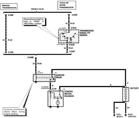

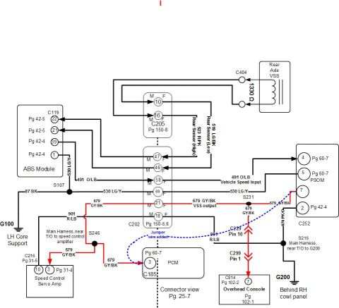
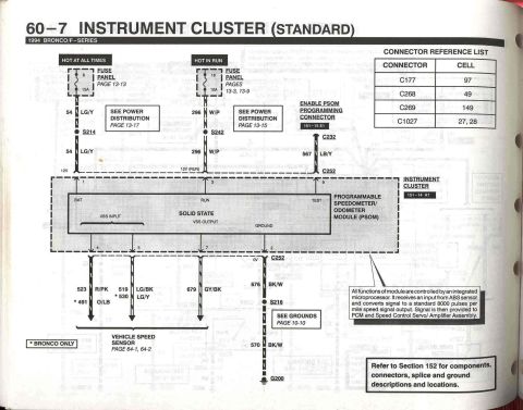
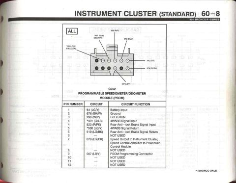



Wiring diagram of the starter circuit showing the transmission range sensor, starter relay, solenoid, battery, and color-coded wires.
Part of 1992-1996 Ford Bronco Wiring Diagrams
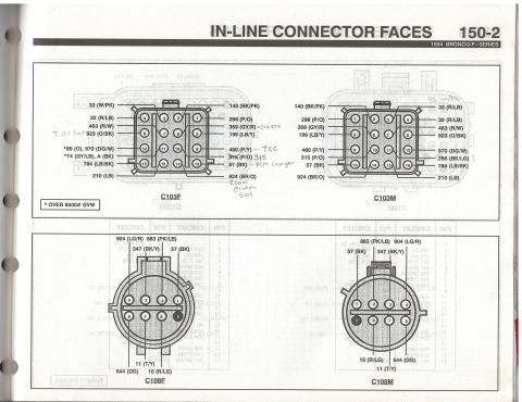
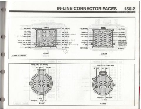
This document is a wiring diagram for the starting (starter/charging-related) system of a Ford vehicle, showing the circuit from the ignition/start feed through to the starter motor. Two configurations are shown at the top: a manual transmission branch and an *E4OD or 4R70W automatic transmission branch, both fed via connector C103 (C103F/C103M) using circuit 32, wire color R/LB (red/light blue). On the automatic side, 12V (START) passes through connector C1012 into the Transmission Range (TR) Sensor, which, per the callout, allows the driver to start the vehicle only in PARK or NEUTRAL. The TR sensor output (12V in P or N) returns through C1012 and C103 on circuit 32 R/LB to the Starter Relay. The relay, which per the second callout controls current flow to the starter motor during engine starting, receives 12V from the battery on a red (R) wire and, when energized, sends 12V through connector C116 on a red wire to the Starter Motor/Solenoid. The battery also feeds the solenoid directly via a red wire, and grounds via black (BK) wires to G101 (body ground) and G103 (engine ground). Connector and ground identifiers include C103F, C103M, C1012, C116, G101, and G103.
Is this accurate? Sign in to help verify it.
Frequently asked questions
- What does the Transmission Range (TR) sensor do in this circuit?
- Per the diagram callout, it allows the driver to start the vehicle only in the "PARK" or "NEUTRAL" position, passing 12V (START) through connector C1012 to output 12V (P or N) toward the starter relay.
- What wire color and circuit number feed the starter relay control?
- Circuit 32, color R/LB (red/light blue), routed through connectors C103F/C103M (and C1012 on automatic transmissions).
- What is the function of the starter relay?
- The callout states it controls current flow to the Starter Motor during engine starting; when energized it sends 12V on a red (R) wire through connector C116 to the starter motor/solenoid.
- Which transmissions does the automatic branch of this diagram cover?
- The E4OD or 4R70W transmissions (marked with an asterisk); a separate branch covers manual transmissions.
- Where are the ground points in this starting circuit?
- The battery grounds through black (BK) wires to G101 (body ground) and G103 (engine ground).






No comments yet.