Ford E4OD Transmission Range (TR) Sensor Connector C1012 Pinout Diagram

Reference · 1992-1996 BroncoAll 411 wiring diagrams
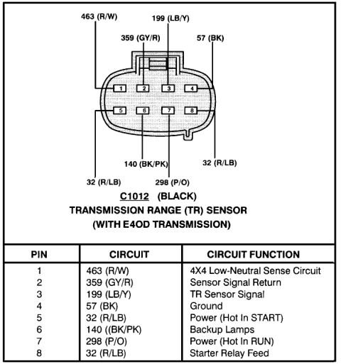









Pinout diagram for the black C1012 Transmission Range (TR) sensor connector on the Ford E4OD transmission, mapping all 8 pins to circuit numbers, wire colors and functions.
Part of 1992-1996 Ford Bronco Wiring Diagrams
This document is a connector pinout diagram for connector C1012 (black), the Transmission Range (TR) Sensor connector used with the E4OD automatic transmission. The upper portion shows the 8-pin connector face with pins numbered 1-4 across the top row and 5-8 across the bottom row, with each cavity labeled by its circuit number and wire color code. The lower portion is a table listing each pin, its circuit number/wire color, and its circuit function: Pin 1-463 (R/W), 4x4 Low-Neutral Sense Circuit; Pin 2-359 (GY/R), Sensor Signal Return; Pin 3-199 (LB/Y), TR Sensor Signal; Pin 4-57 (BK), Ground; Pin 5-32 (R/LB), Power (Hot In START); Pin 6-140 (BK/PK), Backup Lamps; Pin 7-298 (P/O), Power (Hot In RUN); Pin 8-32 (R/LB), Starter Relay Feed. A reader can use this diagram to identify wire colors and functions when diagnosing TR sensor (neutral safety switch) issues such as no-start, no backup lamps, or incorrect gear indication on an E4OD-equipped vehicle. The document itself does not state a year, make, or model; it was uploaded to a 1995 Ford Bronco gallery.
Is this accurate? Sign in to help verify it.
Frequently asked questions
- What is connector C1012?
- C1012 is the black connector for the Transmission Range (TR) Sensor used with the E4OD transmission; it has 8 pins.
- Which pin on the E4OD TR sensor connector is the TR sensor signal?
- Pin 3, circuit 199 (LB/Y: light blue/yellow), is the TR Sensor Signal.
- Which wire feeds the starter relay from the TR sensor?
- Pin 8, circuit 32 (R/LB: red/light blue), is the Starter Relay Feed. Pin 5 is also circuit 32 (R/LB) and is Power (Hot In START).
- Which pin controls the backup lamps?
- Pin 6, circuit 140 (BK/PK: black/pink), is the Backup Lamps circuit.
- Where is ground on the C1012 connector?
- Pin 4, circuit 57 (BK: black), is Ground.






No comments yet.