1995 Ford Bronco Air Bag System Wiring Diagram - Diagnostic Monitor & Sensors

Reference · 1992-1996 BroncoAll 411 wiring diagrams
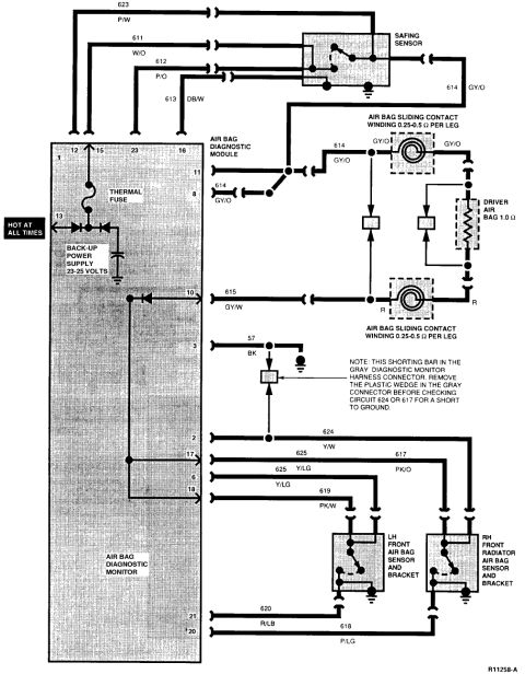




Airbag (SRS) wiring diagram showing the air bag diagnostic module/monitor, 23-25V back-up power supply, safing sensor, sliding contacts (0.25-0.5 ohm/leg) and LH/RH front radiator sensors.
Part of 1992-1996 Ford Bronco Wiring Diagrams
This document is a wiring schematic (reference R11258-A) for a Ford air bag (SRS) system, uploaded to a 1995 Ford Bronco gallery. It shows the Air Bag Diagnostic Monitor with its internal thermal fuse and back-up power supply (23-25 volts), a 'Hot at All Times' feed at pin 13, and connections to the Safing Sensor, Air Bag Diagnostic Module, driver air bag (1.0 Ω), the air bag sliding contact (clockspring, winding 0.25-0.5 Ω per leg), and the LH front and RH front radiator air bag sensors and brackets. Numbered circuits with wire colors are labeled throughout: 623 P/W, 611 W/O, 612 P/O, 613 DB/W, 614 GY/O, 615 GY/W, 57 BK (ground), 624 Y/W, 625 Y/LG, 617 PK/O, 619 PK/W, 620 R/LB, and 618 P/LG. Diagnostic monitor connector pins 1, 2, 3, 6, 8, 10, 11, 12, 13, 15, 16, 17, 18, 20, 21, and 23 are identified. A service note explains that a shorting bar exists in the gray diagnostic monitor harness connector and that the plastic wedge must be removed from the gray connector before checking circuit 624 or 617 for a short to ground. Useful for diagnosing air bag lamp codes and circuit continuity/resistance checks.
Is this accurate? Sign in to help verify it.
Frequently asked questions
- What is the resistance of the driver air bag on this diagram?
- The driver air bag is shown as 1.0 Ω, and the air bag sliding contact winding is 0.25-0.5 Ω per leg.
- What voltage does the air bag back-up power supply provide?
- The back-up power supply inside the Air Bag Diagnostic Monitor is rated 23-25 volts.
- What must be done before checking circuit 624 or 617 for a short to ground?
- Per the note, a shorting bar is in the gray diagnostic monitor harness connector; you must remove the plastic wedge in the gray connector before checking circuit 624 or 617 for a short to ground.
- What wire colors are used for the air bag safing sensor circuits?
- Circuit 623 is P/W, 611 is W/O, 612 is P/O, 613 is DB/W, and 614 is GY/O.
- Which circuits connect the diagnostic monitor to the front crash sensors?
- Circuits 624 Y/W, 617 PK/O, 625 Y/LG, 619 PK/W, 620 R/LB, and 618 P/LG run to the LH front air bag sensor and RH front radiator air bag sensor and brackets.






No comments yet.