Ford MLP Sensor Connector Wiring Diagram - Pin 46 & Pin 30 (1995 Bronco E4OD)

Reference · 1992-1996 BroncoAll 411 wiring diagrams
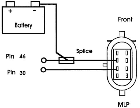








Wiring diagram showing a battery jumpered through a splice to MLP connector pins 46 and 30.
Part of 1992-1996 Ford Bronco Wiring Diagrams
This scanned wiring diagram illustrates the connector and test/wiring hookup for the MLP (Manual Lever Position) sensor, viewed from the front of the connector. The drawing shows a battery at the upper left with its positive (+) and negative (-) terminals marked. A wire runs from the battery's negative terminal down to a marked splice, which then connects to a lead labeled Pin 46. A second lead labeled Pin 30 runs directly to the connector. On the right side of the diagram, an oval-shaped connector housing labeled 'Front' at the top and 'MLP' at the bottom is drawn with two vertical rows of terminal cavities; the Pin 46 and Pin 30 wires terminate at two terminals in the left row of this connector. The document was uploaded to a 1995 Ford Bronco gallery among other transmission-related diagrams, suggesting it relates to the transmission's manual lever position sensor circuit (which reports gear selector position to the powertrain control module). The diagram itself contains no year, model, part numbers, wire colors, or amperage information, only the battery, splice, pin numbers 46 and 30, and the MLP connector face orientation.
Is this accurate? Sign in to help verify it.
Frequently asked questions
- What connector does this diagram show?
- It shows the MLP connector viewed from the front, an oval connector with two vertical rows of terminals.
- Which pins are wired in this MLP diagram?
- Pin 46 and Pin 30. Pin 46 connects through a splice to the battery's negative terminal, and both pins lead to terminals on the left row of the MLP connector.
- Where does the splice connect in this diagram?
- The splice is on the wire between the battery negative (-) terminal and the Pin 46 lead.
- How is the connector oriented in the drawing?
- The connector is shown from the front, with 'Front' labeled at the top and 'MLP' labeled at the bottom of the connector housing.






No comments yet.