Home/
Registry/
Ford/
Bronco/
1987-1991/
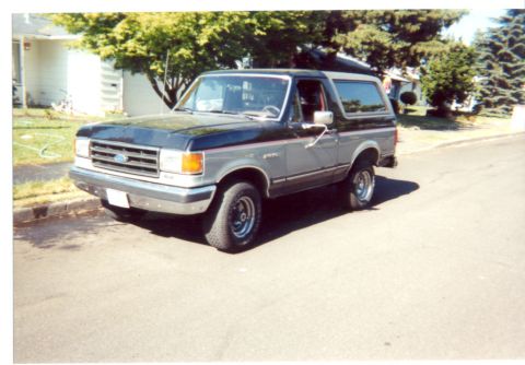
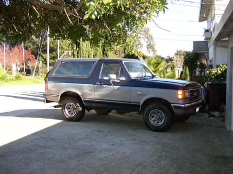
1991 Ford Bronco/
Photo
supermotors.net/registry/media/1089172
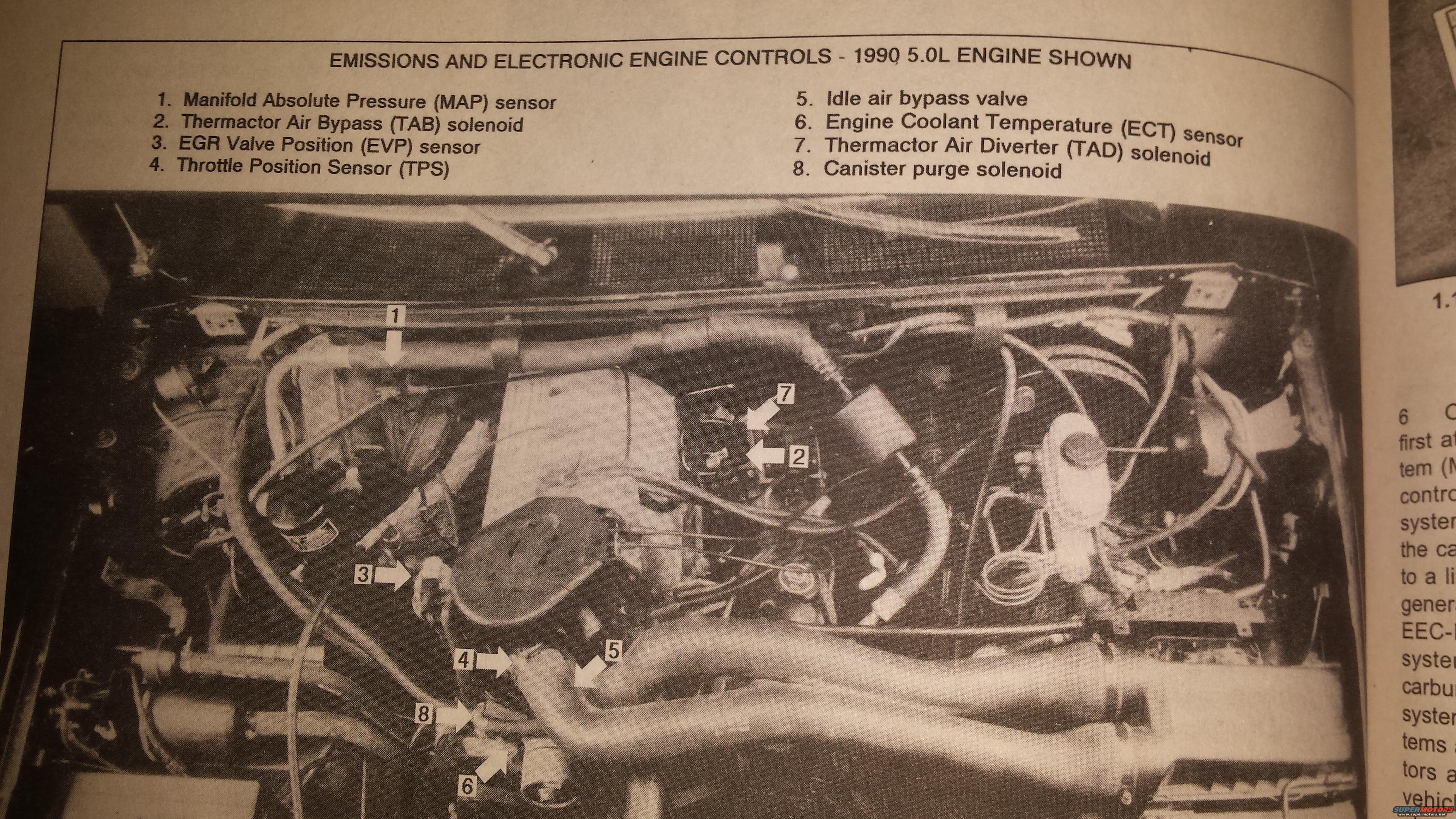
1990 Ford Bronco 5.0L Emissions and Electronic Engine Controls Diagram
Reference · 1987-1991 BroncoAll 112 schematics

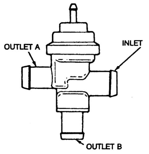
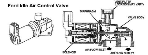
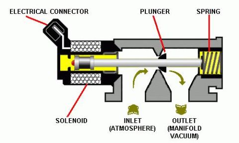
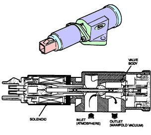

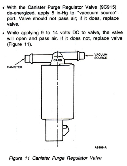
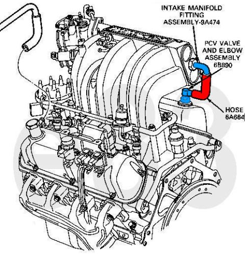
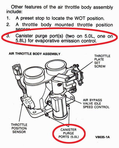
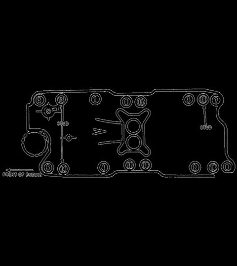
Emissions and engine controls on a 1990 5.0L, locating MAP, TPS, EVP and ECT sensors, TAB and TAD solenoids, idle air bypass valve and canister purge.
Part of 1987-1991 Ford Bronco Schematics
This page is a photographed repair-manual illustration titled "Emissions and Electronic Engine Controls - 1990 5.0L Engine Shown." It is a black-and-white photo of the engine compartment with numbered arrows pointing to eight emissions and engine-control components. The caption names them: 1, Manifold Absolute Pressure (MAP) sensor; 2, Thermactor Air Bypass (TAB) solenoid; 3, EGR Valve Position (EVP) sensor; 4, Throttle Position Sensor (TPS); 5, Idle air bypass valve; 6, Engine Coolant Temperature (ECT) sensor; 7, Thermactor Air Diverter (TAD) solenoid; and 8, Canister purge solenoid. In the photo, the MAP sensor (1) is near the top left by the firewall. The TAD (7) and TAB (2) solenoids are grouped together toward the center. The EVP sensor (3) is on the left side of the intake. The TPS (4), idle air bypass valve (5), canister purge solenoid (8) and ECT sensor (6) are clustered near the front of the engine by the large air intake tube. The right edge of the page shows part of the facing page, cut off. It includes a figure label beginning "1.1" and fragments of body text mentioning "EEC-" and "carbu[...]". This makes the page a useful locator reference for 5.0L engine-control sensors and solenoids.
This document covers 1990, which may differ from this 1991 Ford Bronco.
Is this accurate? Sign in to help verify it.
Frequently asked questions
- Where is the MAP sensor on the 5.0L engine shown?
- The Manifold Absolute Pressure (MAP) sensor is item 1. The arrow points to it near the top left of the engine compartment, close to the firewall.
- Which emissions components does this diagram identify?
- It identifies eight: the MAP sensor, the Thermactor Air Bypass (TAB) solenoid, the EGR Valve Position (EVP) sensor, the Throttle Position Sensor (TPS), the idle air bypass valve, the Engine Coolant Temperature (ECT) sensor, the Thermactor Air Diverter (TAD) solenoid and the canister purge solenoid.
- Where are the TAB and TAD solenoids located?
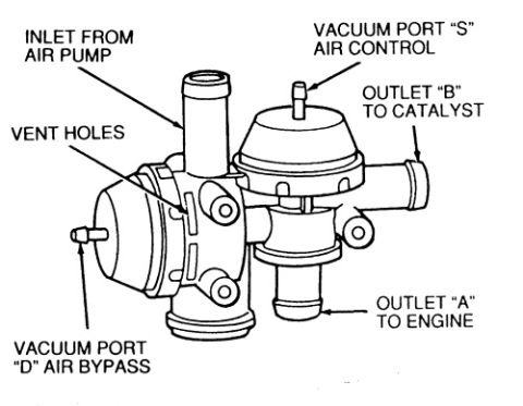
- The TAB solenoid (item 2) and the TAD solenoid (item 7) are mounted next to each other near the center of the engine compartment in the photo.
- What engine is shown in this illustration?
- The caption reads "1990 5.0L Engine Shown."
- Where are the TPS, idle air bypass valve and ECT sensor?
- The TPS (4), idle air bypass valve (5), canister purge solenoid (8) and ECT sensor (6) are grouped together near the lower center of the photo, by the large intake air tube.


No comments yet.