Home/
Registry/
Ford/
Bronco/
1987-1991/
“Vanilla Gorilla”/
Photo
supermotors.net/registry/media/1102044
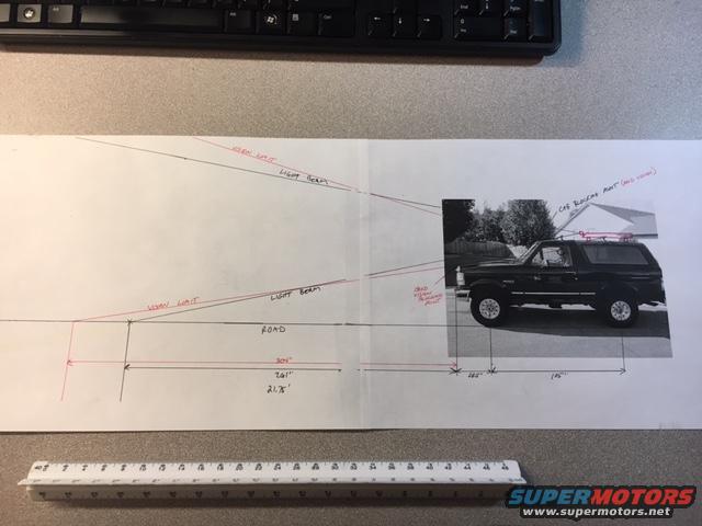
Ford Bronco LED Light Bar Beam Range Diagram - Roof Rack Mount Aiming Sketch
Reference · 1987-1991 BroncoAll 112 schematics













Hand-drawn schematic of headlight beam aiming geometry with road line, legal limit and measurements over a Bronco photo.
Part of 1987-1991 Ford Bronco Schematics
This document is a hand-drawn schematic (photographed on a desk with a scale ruler) analyzing the projection range of auxiliary lights mounted on a Ford Bronco. A side-view photograph of the Bronco, fitted with a roof rack and camper shell, is pasted onto the drawing. From the truck, two sets of beam lines are drawn: red lines labeled 'VISION LIGHT' and black lines labeled 'LIGHT BEAM', converging toward a point on the 'ROAD' baseline to the left. A red callout identifies the 'CAB RACK MNT' (cab rack mount) location on the roof, and another red note near the front indicates a ground viewing point. Dimension lines along the bottom give beam-throw distances of roughly 304 feet (red) and 261 feet (black), with additional segments of 21.5 feet and measurements under the vehicle itself (approximately 145 inches). The drawing appears intended to compare where a roof-rack-mounted LED light bar's beam meets the road versus other mounting positions, helping the owner decide on light bar placement and aim. Numbers are handwritten and some are difficult to read with certainty.
Is this accurate? Sign in to help verify it.
Frequently asked questions
- What does this diagram show for the Ford Bronco?
- It shows a side-view beam projection sketch comparing 'VISION LIGHT' (red) and 'LIGHT BEAM' (black) lines from lights mounted on the Bronco, projected down to the road surface, with distances marked along the bottom.
- Where is the light bar mounted in this diagram?
- A red callout labeled 'CAB RACK MNT (2nd view)' points to the roof rack on the cab, indicating the light is mounted on the cab rack.
- What beam distances are noted?
- Dimension lines show approximately 304 feet (red dimension) and 261 feet (black dimension) from the truck to where the beams meet the road, plus a 21.5-foot segment and measurements of roughly 145 inches under the vehicle.
- What do the red and black lines represent?
- The red lines are labeled 'VISION LIGHT' and the black lines 'LIGHT BEAM', representing two different beam paths from the mounted lights toward a point on the road.






No comments yet.