Home/
Registry/
Ford/
Probe/
1993-1997/
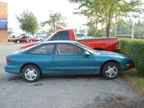
“"Project Car"”/
Photo
supermotors.net/registry/media/291806
V-12 Engine Cutaway 3D Render - Overhead View of Pistons, Cams & Belt Drive

Reference · 1993-1997 ProbeAll 25 schematics



Three-dimensional cutaway schematic illustration of a V engine showing internal pistons, crankshaft and valvetrain components.
Part of 1993-1997 Ford Probe Schematics
This document is not a text-bearing schematic but a 3D rendered illustration of a large V-configuration engine, apparently a V-12 based on the filename and the number of visible cylinders per bank. The render uses a semi-transparent 'ghosted' block and cylinder heads so internal components are visible: white pistons and connecting rods on a common crankshaft, dual overhead camshaft valvetrains on each bank with green-rendered valve springs and dark valves and cam lobes, and a cyan-and-black front-end accessory/timing drive with pulleys and belts at the front of the engine. The engine is shown from a front three-quarter overhead angle against a black background. Because the image contains no legends, callouts, torque specifications, part numbers, or any other text, a reader can learn only the general layout and relative arrangement of internal engine components (piston/rod/crank geometry, overhead cam placement, belt routing at the front cover) rather than any vehicle-specific service data. It appears to be a companion illustration to another render in the same album (timingchain2.jpg) rather than a factory service document.
Is this accurate? Sign in to help verify it.
Frequently asked questions
- What does this image show?
- A 3D rendered cutaway of a V-configuration engine with transparent block, showing pistons, connecting rods, crankshaft, overhead camshafts with valve springs, valves, and front pulley/belt drive.
- Does the image contain any fuse, wiring, or torque specification information?
- No. There is no text of any kind in the image, no labels, legends, part numbers, or specifications.
- Can the valvetrain layout be seen?
- Yes. Each cylinder bank shows overhead camshafts acting on valves with green-rendered valve springs, visible through the transparent cylinder heads.
- Is the front accessory or timing drive visible?
- Yes. Cyan pulleys with black belts are shown at the front of the engine, indicating the belt-drive arrangement.
No comments yet.