Home/
Registry/
Ford/
Bronco/
1987-1991/
1991 Ford Bronco/
Photo
supermotors.net/registry/media/503389
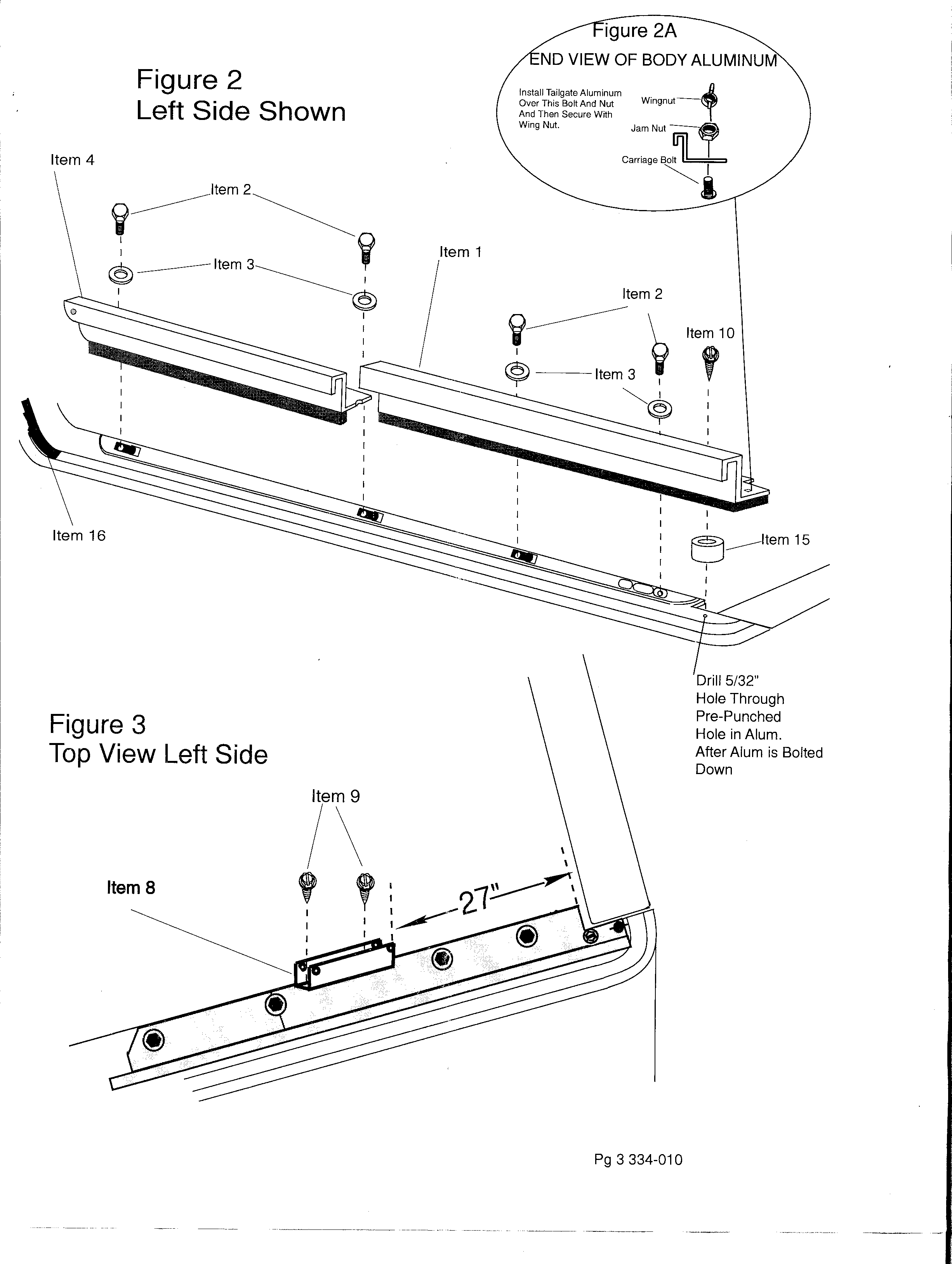
Soft Top Rail Installation Diagram Pg 3 (334-010) - Ford Bronco Aluminum Rails
Reference · 1987-1991 BroncoAll 64 exploded parts diagrams



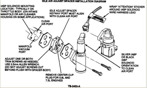
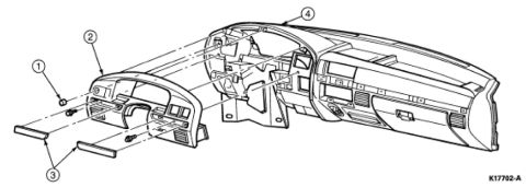
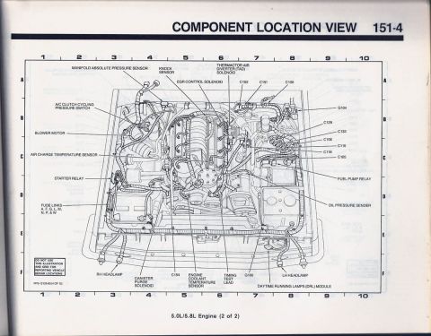
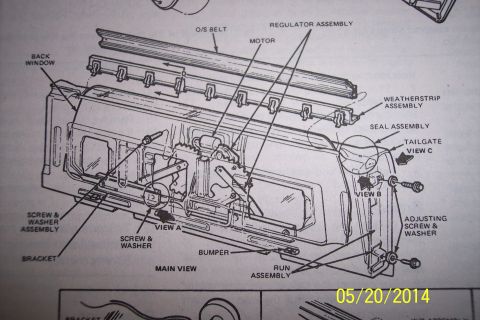










Exploded assembly drawing showing left-side body aluminum trim, fasteners, and item callouts with dimensions.
Part of 1987-1991 Ford Bronco Exploded Parts Diagrams
This is page 3 of an installation instruction set (document number 334-010) showing exploded-view assembly diagrams for mounting aluminum rails along the left side of a vehicle body, most likely for a soft top or tonneau cover kit. Figure 2 ('Left Side Shown') is an exploded view showing how two aluminum rail sections (Item 1 and Item 4) are fastened along the body rail using bolts (Item 2), washers (Item 3), a screw (Item 10), a spacer (Item 15), and a trim/seal piece (Item 16). Figure 2A is an inset end view of the body aluminum showing a carriage bolt, jam nut, and wingnut, with a note to install the tailgate aluminum over the bolt and nut and secure it with the wing nut. A callout instructs the installer to drill a 5/32" hole through the pre-punched hole in the aluminum after the aluminum is bolted down. Figure 3 ('Top View Left Side') shows a bracket (Item 8) secured with two screws (Item 9) positioned 27 inches from the rear corner of the rail. No vehicle year, make, or model is stated on this page.
Is this accurate? Sign in to help verify it.
Frequently asked questions
- What size hole do I drill in the aluminum rail?
- The diagram instructs to drill a 5/32" hole through the pre-punched hole in the aluminum after the aluminum is bolted down.
- How is the tailgate aluminum secured according to Figure 2A?
- Figure 2A (End View of Body Aluminum) shows a carriage bolt with a jam nut; the tailgate aluminum is installed over this bolt and nut and then secured with a wing nut.
- Where is the Item 8 bracket positioned in Figure 3?
- In Figure 3 (Top View Left Side), the Item 8 bracket is fastened with two Item 9 screws at a location 27 inches from the rear end of the rail.
- What hardware attaches the aluminum rails in Figure 2?
- The rails (Items 1 and 4) are attached with bolts (Item 2), washers (Item 3), a screw (Item 10), and a spacer (Item 15); Item 16 is a trim/seal piece at the front.






No comments yet.