Home/
Registry/
Ford/
Bronco/
1987-1991/
1991 Ford Bronco/
Photo
supermotors.net/registry/media/612592
1991 Ford Bronco Single Exhaust Routing Diagram - Frame & Body Layout Sketch

Reference · 1987-1991 BroncoAll 110 schematics
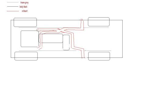













Top-down chassis schematic showing one exhaust-routing layout, with a legend for frame, body and exhaust lines.
Part of 1987-1991 Ford Bronco Schematics
This document is a simple hand-drawn (CAD/paint-style) top-view schematic showing a single exhaust routing plan for a Ford Bronco, uploaded to a 1991 Ford Bronco gallery on SuperMotors.net. The only text present is a three-line color legend at the top left: grey lines represent the frame, black lines represent the body, and red lines represent the exhaust. The drawing itself shows a rectangular body outline with four rounded rectangles at the corners (tires/wheels), two horizontal grey frame rails, and centered black shapes representing the engine, transmission, and driveline components. A red line traces the proposed single exhaust path: it starts at the engine area, loops around the transmission/transfer case region, runs along the passenger-side frame rail toward the rear, and terminates with a small vertical outlet near the right (front-passenger side of the drawing) between the frame rail and body edge. Companion files in the same album (exhaust dual 1 and 2) suggest this is one of several exhaust-routing concepts being compared. No part numbers, dimensions, pipe diameters, years, models, or other specifications are given anywhere in the document; it serves purely as a conceptual routing sketch.
Is this accurate? Sign in to help verify it.
Frequently asked questions
- What do the line colors mean in this exhaust diagram?
- Per the legend: grey lines represent the frame, black lines represent the body, and red lines represent the exhaust routing.
- What does this schematic show?
- A top-down sketch of a vehicle with frame rails (grey), body/component outlines (black), and a red line tracing a single exhaust route from the engine area rearward along the frame.
- Does the diagram include pipe sizes, part numbers, or measurements?
- No. The only text in the document is the three-item color legend; no dimensions, part numbers, or specifications are shown.
- Is this a single or dual exhaust layout?
- This drawing shows one continuous red exhaust path (a single exhaust routing); companion files in the album depict dual exhaust versions.






No comments yet.