Home/
Registry/
Ford/
Bronco/
1987-1991/
1991 Ford Bronco/
Photo
supermotors.net/registry/media/612593
1991 Ford Bronco Dual Exhaust Routing Diagram - Frame & Body Layout Sketch

Reference · 1987-1991 BroncoAll 110 schematics
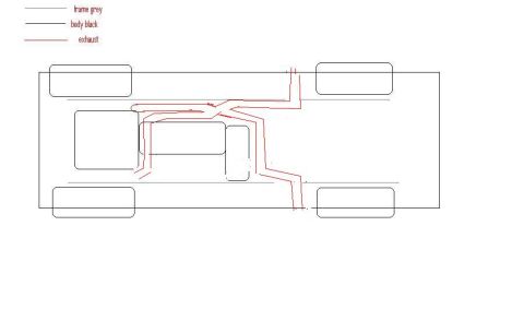













Top-down chassis schematic showing a dual exhaust-routing layout, with a legend for frame, body and exhaust lines.
Part of 1987-1991 Ford Bronco Schematics
This document is a simple, hand-drawn (computer-sketched) schematic showing a proposed or actual dual exhaust routing on a truck-style vehicle, viewed from above (top-down plan view). A three-line legend in the upper-left corner identifies the drawing conventions: grey lines represent the frame, black lines represent the body, and red lines represent the exhaust. The drawing shows the vehicle body outline with four wheels at the corners, two grey frame rails running lengthwise, and central rounded shapes representing the drivetrain (engine, transmission, transfer case). Red exhaust lines run from both sides of the engine area, converge/route around the drivetrain, and split into two pipes that route over or along the frame and exit toward the rear passenger-side area of the vehicle. There are no dimensions, part numbers, pipe diameters, torque values, or year/model identification anywhere in the drawing. Based on the uploader's filing, it illustrates a dual exhaust layout concept for a 1991 Ford Bronco, and it is part of a set that also includes a second dual-exhaust page and a single-exhaust comparison drawing. A reader can learn the general routing path intended for dual exhaust pipes relative to the frame and body, but no specific specifications.
Is this accurate? Sign in to help verify it.
Frequently asked questions
- What do the different line colors mean in this exhaust diagram?
- Per the legend: grey lines represent the frame, black lines represent the body, and red lines represent the exhaust.
- What does this diagram show?
- A top-down schematic of a vehicle showing the body outline, four wheels, grey frame rails, central drivetrain shapes, and a red dual exhaust routing running from the engine area to the rear of the vehicle.
- Does this diagram include pipe sizes, part numbers, or measurements?
- No. The only text in the document is the three-item legend (frame grey, body black, exhaust); no dimensions, part numbers, or specifications are shown.
- How does the exhaust route relative to the frame in this drawing?
- The red exhaust lines run from the engine area, cross over/along the grey frame rails, and split into two pipes exiting toward the rear on one side of the vehicle.






No comments yet.