Home/
Registry/
Ford/
Bronco/
1980-1986/
“Still Pending”/
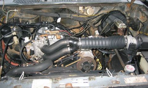
Photo
supermotors.net/registry/media/825048
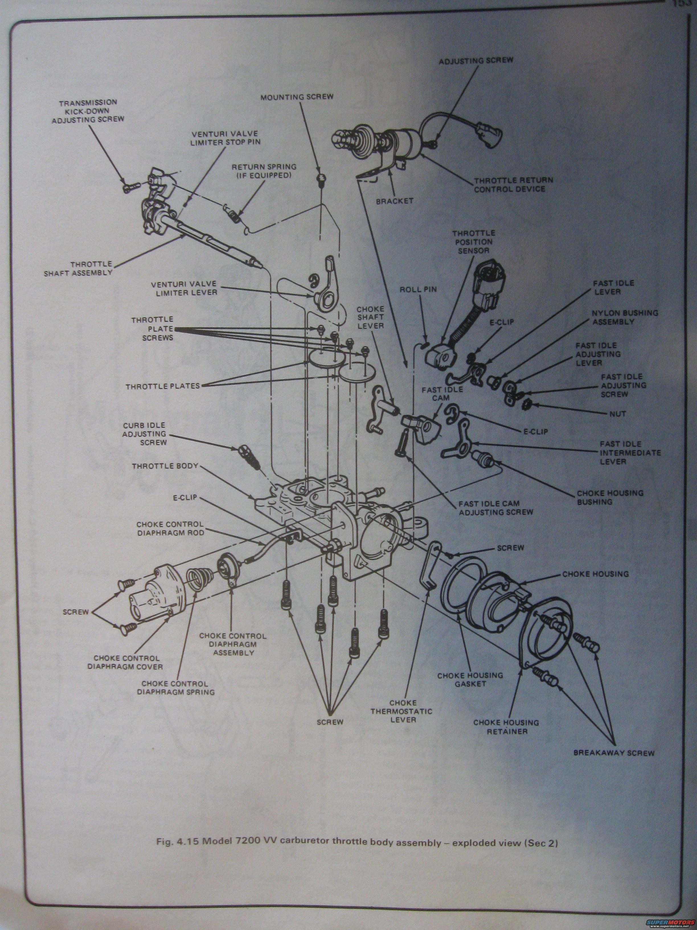
Ford 7200 VV Carburetor Throttle Body Exploded View Diagram - Fig 4.15
Reference · 1980-1986 BroncoAll 61 exploded parts diagrams


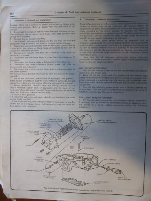
Exploded view of the Motorcraft 7200 VV carburetor throttle body, labeling transmission kick-down screw, venturi valve limiter, choke control diaphragm and choke housing parts.
Part of 1980-1986 Ford Bronco Exploded Parts Diagrams
This document is a single page (page 153) from an automotive service manual showing Figure 4.15, an exploded-view illustration of the throttle body assembly for the Ford Model 7200 VV (Variable Venturi) carburetor. The diagram identifies every component of the throttle body with labeled callouts, including the throttle shaft assembly, transmission kick-down adjusting screw, venturi valve limiter stop pin and lever, throttle plates and their screws, curb idle adjusting screw, and the throttle body casting itself. On the choke side, it labels the choke shaft lever, fast idle cam, fast idle lever, fast idle adjusting lever and screw, fast idle intermediate lever, choke housing, choke housing gasket, choke housing retainer, breakaway screws, choke thermostatic lever, and choke housing bushing. It also shows the choke control diaphragm assembly (rod, cover, spring), the throttle position sensor, throttle return control device with bracket and adjusting/mounting screws, plus small hardware such as E-clips, roll pin, nylon bushing assembly, nut, and various screws. A reader can use this figure to identify parts and their assembly order/orientation when disassembling, rebuilding, or reassembling a 7200 VV carburetor throttle body. No torque values, part numbers, or year applicability are printed on the page.
Is this accurate? Sign in to help verify it.
Frequently asked questions
- What does this diagram show?
- It is Figure 4.15, an exploded view of the Model 7200 VV carburetor throttle body assembly, labeling all its components and their assembly relationships.
- What choke components are identified in the 7200 VV throttle body diagram?
- Choke shaft lever, choke housing, choke housing gasket, choke housing retainer, choke housing bushing, choke thermostatic lever, breakaway screws, and the choke control diaphragm assembly with its rod, cover, and spring.
- Which fast idle parts are shown on the 7200 VV carburetor?
- The fast idle cam, fast idle cam adjusting screw, fast idle lever, fast idle adjusting lever, fast idle adjusting screw, fast idle intermediate lever, plus E-clips, a nut, and a nylon bushing assembly.
- Does the 7200 VV throttle body include a throttle position sensor?
- Yes, the diagram labels a throttle position sensor attached via a roll pin, along with a throttle return control device mounted on a bracket with adjusting and mounting screws.
- What idle and kick-down adjustments are shown?
- The diagram labels a curb idle adjusting screw, fast idle adjusting screw, fast idle cam adjusting screw, and a transmission kick-down adjusting screw on the throttle shaft assembly.
No comments yet.