Home/
Registry/
Ford/
Bronco/
1980-1986/
“Still Pending”/
Photo
supermotors.net/registry/media/825049
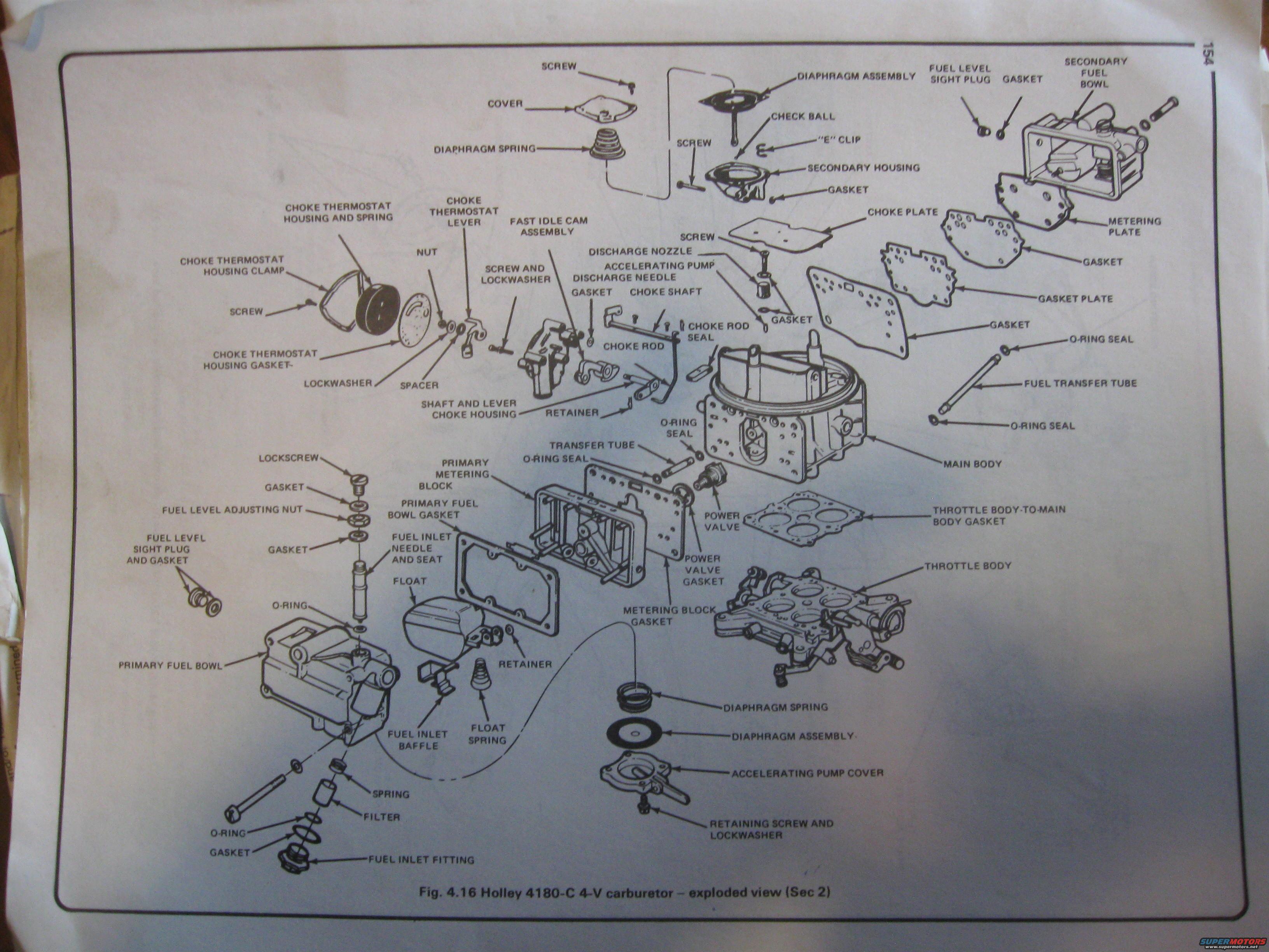
Holley 4180-C 4-Barrel Carburetor Exploded View Diagram - Ford Bronco Manual
Reference · 1980-1986 BroncoAll 61 exploded parts diagrams




Exploded parts diagram of a Holley 4180-C 4-V carburetor with all gaskets, jets, floats and bodies labeled.
Part of 1980-1986 Ford Bronco Exploded Parts Diagrams
This document is a scanned page (page 154) from an automotive service manual showing Figure 4.16, an exploded-view parts diagram of the Holley 4180-C 4-V (four-venturi/four-barrel) carburetor, labeled as being in Section 2. The illustration breaks the carburetor down into its individual components with callout labels for each part. Major assemblies shown include the main body, throttle body, primary and secondary fuel bowls, primary metering block, metering plate, and the choke system (choke thermostat housing and spring, thermostat lever, choke plate, choke shaft, choke rod, fast idle cam assembly, and shaft-and-lever choke housing). Fuel system components identified include the fuel inlet fitting, filter, spring, fuel inlet needle and seat, fuel level adjusting nut, fuel level sight plugs, float, float spring, fuel inlet baffle, power valve and power valve gasket, and fuel transfer tube with O-ring seals. The accelerating pump system is detailed with its diaphragm assembly, diaphragm spring, pump cover, discharge nozzle, discharge needle, and check ball. Numerous gaskets, O-rings, screws, lockwashers, retainers, and an "E" clip are also labeled. A reader can use this diagram to identify parts and their assembly order when disassembling, rebuilding, or reassembling a Holley 4180-C carburetor.
Is this accurate? Sign in to help verify it.
Frequently asked questions
- What carburetor is shown in this diagram?
- The diagram is Fig. 4.16, an exploded view of the Holley 4180-C 4-V (four-barrel) carburetor.
- What choke components are shown in the Holley 4180-C exploded view?
- The choke system includes the choke thermostat housing and spring, choke thermostat housing clamp and gasket, choke thermostat lever, fast idle cam assembly, choke plate, choke shaft, choke rod, choke rod seal, and the shaft-and-lever choke housing.
- What parts make up the fuel inlet on this carburetor?
- The fuel inlet consists of the fuel inlet fitting, gasket, O-ring, filter, spring, fuel inlet baffle, and the fuel inlet needle and seat, along with the fuel level adjusting nut, gaskets, and lockscrew.
- Does the Holley 4180-C have a metering block on both sides?
- Per the diagram, the primary side uses a primary metering block with a metering block gasket, while the secondary side uses a metering plate with a gasket and gasket plate.
- What accelerating pump parts are shown?
- The accelerating pump components include the diaphragm assembly, diaphragm spring, accelerating pump cover with retaining screw and lockwasher, the accelerating pump discharge needle, discharge nozzle, and a check ball.




No comments yet.