Ford Bronco/F-Series Steering Column & Transmission Indicator Exploded Diagram

Reference · 1987-1991 BroncoAll 61 exploded parts diagrams

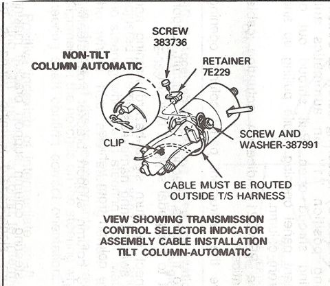
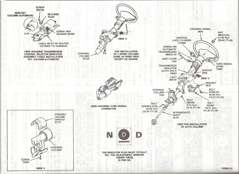











Ford steering column exploded illustration: tilt and non-tilt automatic columns, shift indicator cable routing, ignition lock cylinder and intermediate shaft with torque specs (45-68 N-m steering wheel nut).
Part of 1987-1991 Ford Bronco Exploded Parts Diagrams
This is a scanned exploded parts diagram from a Ford factory service manual (figure code G2940-2J) showing steering column disassembly and the installation of the transmission control selector indicator (shift indicator) assembly. Multiple views are shown: a main exploded view for installing an automatic-transmission column, a view of the transmission control selector indicator cable installation on a tilt column (with a non-tilt column automatic inset), a view of the turn signal connector, and a detail of the steering column shroud (part 3C771) with screw 55391. Callouts identify major components with Ford basic part numbers, including the steering wheel (3600), ignition lock cylinder (11A606), shift lever (7202), turn signal lever (13305), transmission indicator (7B053, auto only), shroud (3530), bracket (3676), steering column (7200 and 3C529), and intermediate shaft (3E751). Fastener torque specifications are given, e.g. steering wheel nut 382412-S2 at 41-56 N·m (30-42 ft-lb), bolt 57050-S2 at 26-36 N·m (19-27 ft-lb), bolt 389185 at 8-13 N·m (6-10 ft-lb), bolt 383481 at 18-51 N·m (13-38 ft-lb), and bolt N605802-S100 at 45-68 N·m (33-50 ft-lb). Notes state the indicator cable must be routed outside the turn signal harness, and the indicator flag must totally fill the adjustment window under the 'D' (D for C6).
Is this accurate? Sign in to help verify it.
Frequently asked questions
- What is the steering wheel nut torque spec shown in this diagram?
- Nut 382412-S2 is torqued to 41-56 N·m (30-42 ft-lb).
- How is the transmission indicator adjusted according to this diagram?
- The indicator flag must totally fill the adjustment window under the 'D' (D for C6).
- How must the transmission control selector indicator cable be routed?
- The cable must be routed outside the turn signal (T/S) harness.
- What torque specs are given for the steering column mounting bolts?
- Bolt 57050-S2: 26-36 N·m (19-27 ft-lb); bolt 389185: 8-13 N·m (6-10 ft-lb); bolt 383481: 18-51 N·m (13-38 ft-lb); intermediate shaft bolt N605802-S100: 45-68 N·m (33-50 ft-lb).
- What Ford part numbers identify the main steering column components?
- Steering wheel 3600, ignition lock cylinder 11A606, shift lever 7202, turn signal lever 13305, transmission indicator 7B053, shroud 3530, steering column 7200, steering column shroud 3C771, intermediate shaft 3E751, bracket 3676.






No comments yet.