Ford Bronco Transmission Shift Indicator Cable Installation Diagram - Tilt Column

Reference · 1987-1991 BroncoAll 61 exploded parts diagrams

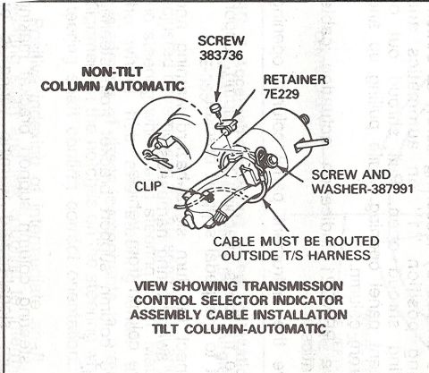
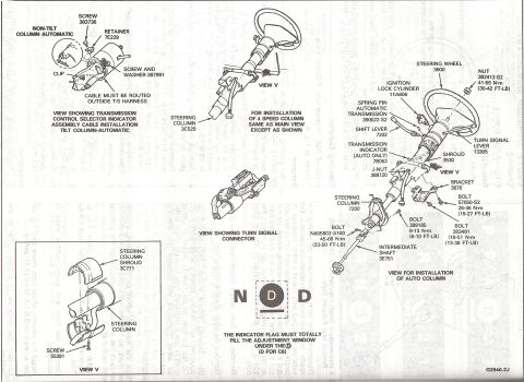










Ford detail illustration of transmission control selector indicator cable installation on a non-tilt automatic column: screw 383736, retainer 7E229, screw-and-washer 387991, cable routed outside T/S harness.
Part of 1987-1991 Ford Bronco Exploded Parts Diagrams
This document is an exploded parts diagram from a Ford service reference showing installation of the transmission control selector indicator assembly cable on a tilt steering column with an automatic transmission. The main illustration depicts the steering column with callouts identifying the fastening hardware: screw 383736, retainer 7E229, a clip, and a screw-and-washer part number 387991. A circular inset at the upper left shows the corresponding attachment detail for a non-tilt column with automatic transmission. An important routing note states that the cable must be routed outside the turn-signal (T/S) harness. The caption reads 'View Showing Transmission Control Selector Indicator Assembly Cable Installation Tilt Column-Automatic.' A reader can learn which fasteners secure the shift indicator (PRNDL) cable to the column, where the clip and retainer attach, and the required cable routing relative to the turn-signal wiring harness. The diagram itself contains no year, model, or torque information; it was uploaded to a 1990 Ford Bronco gallery, and nothing visible contradicts that application. The scan is clear and all callout text is legible.
Is this accurate? Sign in to help verify it.
Frequently asked questions
- What part numbers are used to attach the transmission shift indicator cable to the steering column?
- The diagram calls out screw 383736, retainer 7E229, a clip, and a screw and washer part number 387991.
- How should the shift indicator cable be routed relative to the turn signal harness?
- The diagram states the cable must be routed outside the T/S (turn signal) harness.
- Does this diagram cover both tilt and non-tilt columns?
- Yes. The main view shows the tilt column automatic installation, and an inset shows the non-tilt column automatic attachment detail.
- What transmission type does this diagram apply to?
- It applies to automatic transmission columns, as stated in the labels 'Non-Tilt Column Automatic' and 'Tilt Column-Automatic'.






No comments yet.