Ford EEC Test Resistor Diagram - 12v to Pins 11 CANP, 31 TAB, 33 EVR, 34 TAD

Reference · 1992-1996 BroncoAll 411 wiring diagrams
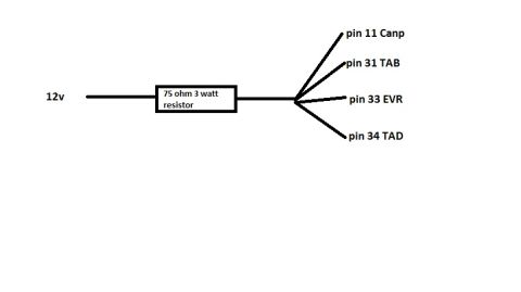














Simple wiring diagram showing 12V through a 75 ohm 3 watt resistor branching to ECU pins 11 Canp, 31 TAB, 33 EVR and 34 TAD.
Part of 1992-1996 Ford Bronco Wiring Diagrams
This is a simple hand-drawn (computer-sketched) wiring diagram uploaded to a 1992 Ford Bronco gallery. It shows a single 12-volt supply line feeding through a 75 ohm, 3 watt resistor, after which the circuit branches into four separate leads. Each lead is labeled with a connector pin number and abbreviation: pin 11 Canp, pin 31 TAB, pin 33 EVR, and pin 34 TAD. The diagram gives no vehicle year, model, connector part number, wire colors, or additional notes, it consists solely of the 12v source, the resistor specification, and the four labeled pin destinations. A reader can learn from this document how to wire a single resistor-protected 12v feed to these four specific pins (commonly used as a dummy-load or test setup for solenoid driver outputs), including the exact resistor value (75 ohms) and power rating (3 watts) required. No fuse information, torque specs, or part numbers appear in the document.
Is this accurate? Sign in to help verify it.
Frequently asked questions
- What resistor value is shown in this diagram?
- A 75 ohm, 3 watt resistor placed in line with the 12v supply.
- Which pins does the 12v circuit connect to after the resistor?
- Pin 11 (Canp), pin 31 (TAB), pin 33 (EVR), and pin 34 (TAD).
- How is the circuit arranged?
- A 12v source feeds through a single 75 ohm 3 watt resistor, then splits into four branches, one to each of the four pins.
- Does the diagram specify wire colors or connector part numbers?
- No, it only shows the 12v source, the resistor spec, and the four pin labels.






No comments yet.