PMGR Starter Motor Cutaway & Exploded Diagram - Planetary Gear Reduction Parts

Reference · 1987-1991 BroncoAll 61 exploded parts diagrams
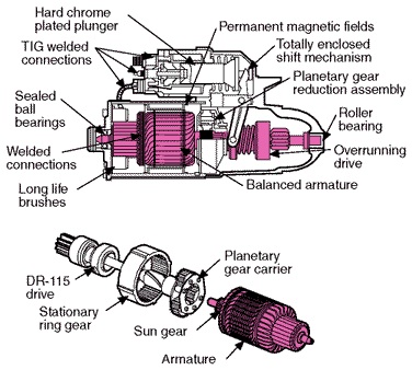








Exploded and cutaway drawing of a gear-reduction starter motor showing the armature, planetary gear carrier, sun gear, brushes and overrunning drive.
Part of 1987-1991 Ford Bronco Exploded Parts Diagrams
This document is an illustrated diagram of a permanent magnet gear reduction (PMGR) starter motor, showing both a labeled cutaway view and an exploded view of the planetary gear reduction assembly. The upper cutaway illustration identifies key design features of the starter: a hard chrome plated plunger, TIG welded connections, permanent magnetic fields, a totally enclosed shift mechanism, the planetary gear reduction assembly, sealed ball bearings, welded connections, a roller bearing, the overrunning drive, long life brushes, and a balanced armature. The lower exploded view breaks down the gear reduction section, labeling the DR-115 drive, the stationary ring gear, the planetary gear carrier, the sun gear, and the armature. A reader can learn how a PMGR starter is internally constructed, where the planetary reduction gearset sits relative to the armature and drive, and which durability features (welded connections, sealed bearings, enclosed shift mechanism) distinguish this design. The document contains no fuse data, wire colors, torque specifications, part numbers other than the DR-115 drive designation, or year/model applicability statements. It appears to be a reference/training-style illustration, filed by the uploader alongside related starter relay and PMGR wiring documents for a 1990 Ford Bronco.
Is this accurate? Sign in to help verify it.
Frequently asked questions
- What are the internal parts of a PMGR starter shown in this diagram?
- The cutaway labels a hard chrome plated plunger, TIG welded connections, permanent magnetic fields, a totally enclosed shift mechanism, planetary gear reduction assembly, sealed ball bearings, welded connections, roller bearing, overrunning drive, long life brushes, and a balanced armature.
- What components make up the planetary gear reduction assembly in the exploded view?
- The exploded view shows the DR-115 drive, stationary ring gear, planetary gear carrier, sun gear, and armature.
- What type of drive is used in this starter?
- The diagram identifies a DR-115 drive with an overrunning drive mechanism.
- What bearings does this starter use?
- The diagram calls out sealed ball bearings and a roller bearing.






No comments yet.