Home/
Registry/
Ford/
Bronco/
1987-1991/
“Hippie Destroyer”/
Photo
supermotors.net/registry/media/102269
Ford Bronco Headlight Assembly Exploded Parts Diagram - Bezel, Bulbs & Lamps

Reference · 1987-1991 BroncoAll 64 exploded parts diagrams



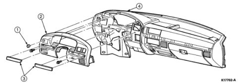
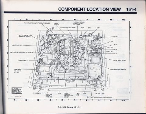
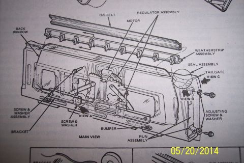



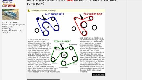








Exploded parts diagram of a headlight, side marker lamp, and bezel assembly with numbered component callouts.
Part of 1987-1991 Ford Bronco Exploded Parts Diagrams
This document is an exploded-view parts illustration of a front headlight assembly and adjacent front lamps for a Ford truck/Bronco-style vehicle. It contains no written text, part numbers, or legend, only numbered callouts 1 through 11 pointing to components. The boxed area (callout 1) shows the composite headlamp assembly: the lens/housing (2), several bulbs and sockets (3, 4, 5, 6), and an adjuster/retainer mechanism with rod (7). Below the box, callout 8 identifies the large headlight bezel or trim panel that surrounds the lamp, callout 11 indicates a small corner lamp lens/housing, and callouts 9 and 10 point to the parking/side-marker lamp's socket and bulb, mounted in the combination lamp housing shown at the lower right. The background sketch shows the vehicle's front fender and body corner to indicate where the assembly mounts. A reader can learn the relative arrangement and disassembly order of the headlamp components, which bulbs and sockets fit the housing, how the adjuster relates to the lamp, and how the bezel and corner/parking lamps assemble around the headlight, but cannot obtain part numbers, torque specs, or applicability years from this page alone, since none are printed on it.
Is this accurate? Sign in to help verify it.
Frequently asked questions
- What components are shown in this headlight assembly diagram?
- It shows the composite headlamp housing/lens, multiple bulbs and sockets, an adjuster/retainer with rod, the surrounding headlight bezel/trim panel, a corner lamp lens, and the parking/side marker lamp bulb and socket, identified by callouts 1 through 11.
- Does this diagram include part numbers?
- No. The illustration uses only numbered callouts (1-11) with no part numbers, legend, or text visible.
- How many bulbs/sockets are shown in the headlamp assembly?
- The boxed exploded view shows several bulb/socket items (callouts 3, 4, 5, and 6), plus a separate parking/marker lamp bulb and socket (callouts 9 and 10).
- What is the large panel labeled 8?
- Callout 8 points to the headlight trim bezel/mounting panel that surrounds the headlamp and corner lamp on the front of the vehicle.






No comments yet.