Home/
Registry/
Ford/
Bronco/
1987-1991/
“Hippie Destroyer”/
Photo
supermotors.net/registry/media/102270
1987 Ford Bronco Grille & Mount Panel Exploded Parts Diagram - Emblem, Header

Reference · 1987-1991 BroncoAll 64 exploded parts diagrams



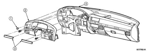
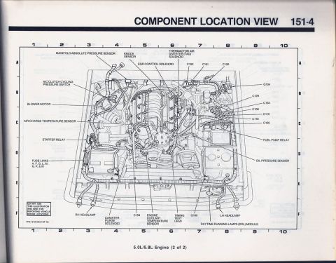
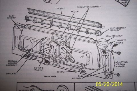



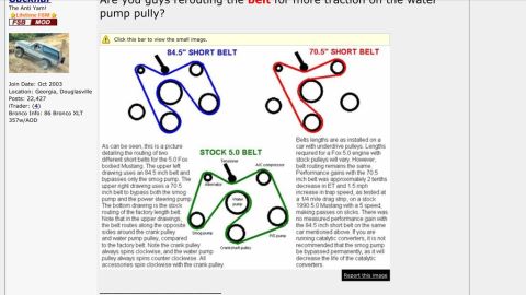








Exploded parts diagram of a front grille, emblem, and radiator support with numbered component callouts.
Part of 1987-1991 Ford Bronco Exploded Parts Diagrams
This document is a black-and-white exploded parts diagram (line drawing) showing the front grille and mounting components of a vehicle. Three parts are identified by numbered callouts: item 1 is the main grille assembly, drawn as a wide panel with multiple horizontal and vertical slot openings and a central oval provision for an emblem; item 2 is a small oval emblem or badge shown detached at the upper left; item 3 is the header/mount panel (radiator support / front-end panel) positioned above and behind the grille, featuring openings for headlight or lamp assemblies on its ends. The drawing illustrates the relative positions and orientation of these components as they assemble at the front of the vehicle. No part numbers, legend text, model names, years, or torque specifications appear anywhere in the image, the only text present is the three callout numbers. A reader can use this diagram to understand how the grille, emblem, and mount panel relate to each other during removal or installation, but must consult an accompanying parts list (not shown) to identify part numbers or names for the numbered items.
Is this accurate? Sign in to help verify it.
Frequently asked questions
- What parts are shown in this exploded diagram?
- Three components are shown: the grille assembly (callout 1), a small oval emblem/badge (callout 2), and the header/mount panel above the grille (callout 3).
- Does this diagram list any part numbers or amperages?
- No. The only text visible in the document is the three callout numbers 1, 2, and 3; no part numbers, legend, or specifications are printed.
- How do the grille and mount panel fit together according to the diagram?
- The mount panel (item 3) sits above and behind the grille (item 1), and the oval emblem (item 2) mounts to the central oval area of the grille.
- Which callout identifies the emblem?
- Callout 2 points to the small detached oval emblem shown at the upper left of the drawing.






No comments yet.