SuperMotors SuperMotors SUPERMOTORS Search: try “orange Bronco on 35s”
Home/ Registry/ Ford/ Bronco/ 1987-1991/ “Pale Horse”/ Photo supermotors.net/registry/media/190378

Ford Bronco Rear Driveshaft Exploded Diagram - Double Cardan & Slip Yoke
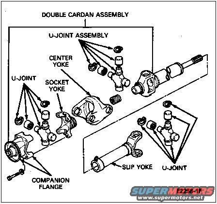
Exploded parts diagram of a double Cardan driveshaft assembly with labeled yokes and U-joints
Exploded parts diagram of a double Cardan driveshaft assembly with labeled yokes and U-jointsOriginal file
Exploded parts diagram of a double Cardan driveshaft assembly with labeled yokes and U-joints

Reference · 1987-1991 BroncoAll 64 exploded parts diagrams

Ford Bronco Rear Driveshaft Exploded Diagram - Double Cardan & Slip Yoke Ford 5.0L V8 PCV Valve & Hose Routing Diagram - 9A474, 6B890, 6A664 Ford 5.8L EFI PCV Valve & Hose Routing Diagram - Part Numbers & Torque Specs Ford Bronco Speed Density Air Intake Tube & Air Cleaner Exploded Diagram 1990 Ford Bronco Air Intake Tube & Air Cleaner MAF - Exploded Parts Diagram Ford IABP Idle Air Adjust Spacer Installation Diagram (TB-2433-A) 5.8L 7.5L 1990 Ford Bronco Dash Panel Removal - Instrument Panel Exploded Diagram 1990 Ford Bronco 5.0L/5.8L Engine Component Location Diagram (151-4) Ford Bronco Tailgate Window Regulator & Motor Exploded Diagram - Rear Glass Ford Bronco 5.8L Secondary Air (Thermactor) System Exploded Parts Diagram Ford 5.0L Secondary Air (Thermactor) System Exploded Parts Diagram - 1990 Bronco PMGR Starter Motor Cutaway & Exploded Diagram - Planetary Gear Reduction Parts 64exploded parts diagrams1987-1991 Ford Bronco More reference Ford towing guide page defining GAW, GAWR, GVW and GVWR with instructions for weighing axles on a scaleManual page Ford 3G Alternator Wiring Diagram - Mega Fuse, Charge Lamp & Wire ColorsWiring diagram Ford 5.0 Fox Mustang Short Belt Routing Diagram - 84.5" & 70.5" vs StockSchematic Ford Canister Purge Regulator Valve (CANP 9C915) Test Procedure - Figure 11Service procedure Welder Input Data Plate - Serial JH229505, Stock 901782, 200/230/460V SpecsSpec plate Magnum Metropolitan Brochure - Ford Bronco/F-Series Suburban-Style ConversionBrochure Tubing Adapter Blueprint 2.00" OD x 1.375" ID x 3" - 1.125"-12 TPI RH ThreadBlueprint Ford Thermactor Combination Valve Diagram - Air Bypass/Control Ports LabeledVacuum routing 1990 Ford Bronco Fuse Panel Diagram: Fuse Positions, Amps & Circuits (11-2)Fuse chart Ford V8 Intake Manifold Bolt Tightening Sequence Diagram - Stud LocationsTorque spec

Exploded parts diagram of a double Cardan driveshaft assembly labeling the center yoke, socket yoke, slip yoke, U-joints and companion flange.

Part of 1987-1991 Ford Bronco Exploded Parts Diagrams

AI caption · Photo 15 of 60

This document is an exploded parts diagram (figure reference E2258-1F) showing the components of a driveshaft double cardan assembly, uploaded to SuperMotors.net as a rear driveshaft reference for a 1990 Ford Bronco. The illustration labels the major components in exploded view: the double cardan assembly as a whole (outlined with a bracket at the top left of the drawing), the U-joint assembly with its cross and bearing caps, the center yoke, the socket yoke, a U-joint with its cross and cap components, and the companion flange with its attaching bolt at the differential end. On the opposite end of the shaft, the diagram identifies the slip yoke and another U-joint with its bearing caps and cross. A reader can learn the assembly order and relative positions of the double cardan (CV-style) joint components, how the U-joints, center yoke, and socket yoke fit together within the double cardan assembly, and how the slip yoke and rear U-joint connect at the other end of the shaft. The diagram contains only callout labels, no part numbers, torque specifications, or year/model applicability text is visible.

Is this accurate? Sign in to help verify it.

Frequently asked questions

What components make up the double cardan assembly in this diagram?
The diagram shows the double cardan assembly includes a U-joint assembly, a center yoke, a socket yoke, and a U-joint, mounted to a companion flange.
What is at the opposite end of the driveshaft from the double cardan joint?
The diagram shows a slip yoke with a U-joint (cross and bearing caps) at the other end of the shaft.
What connects the double cardan assembly to the axle/transfer case side?
A companion flange, shown with an attaching bolt, is at the base of the double cardan assembly.
Does this diagram list part numbers or torque specs?
No. It is an exploded illustration with component name callouts only; the only reference marking is the figure number E2258-1F.


Comments

No comments yet.

More 1987-1991 Broncos