SuperMotors SuperMotors SUPERMOTORS Search: try “orange Bronco on 35s”
Home/ Registry/ Ford/ Bronco/ 1980-1986/ “ToyEater”/ Photo supermotors.net/registry/media/199525

L & L Products engine mount installation instructions, part numb…

L & L Products engine mount installation instructions, part number 03-0495, with driver and passenger side photos
L & L Products engine mount installation instructions, part number 03-0495, with driver and passenger side photosOriginal file
L & L Products engine mount installation instructions, part number 03-0495, with driver and passenger side photos

Reference · 1980-1986 BroncoAll 40 service procedures

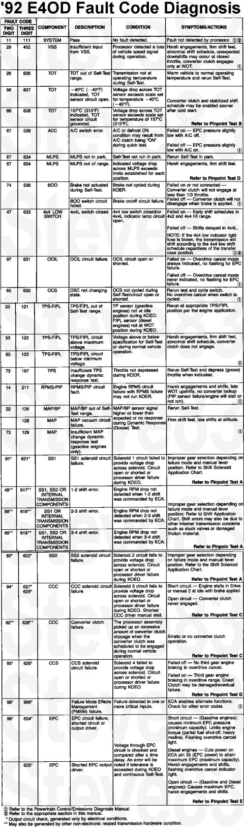
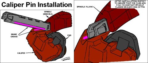
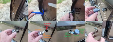
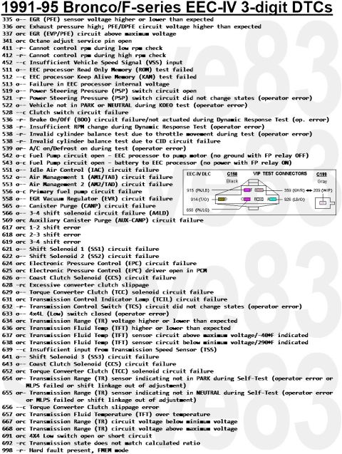
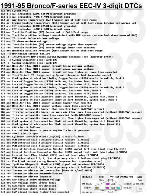
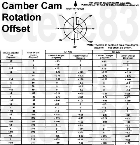
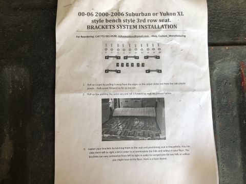
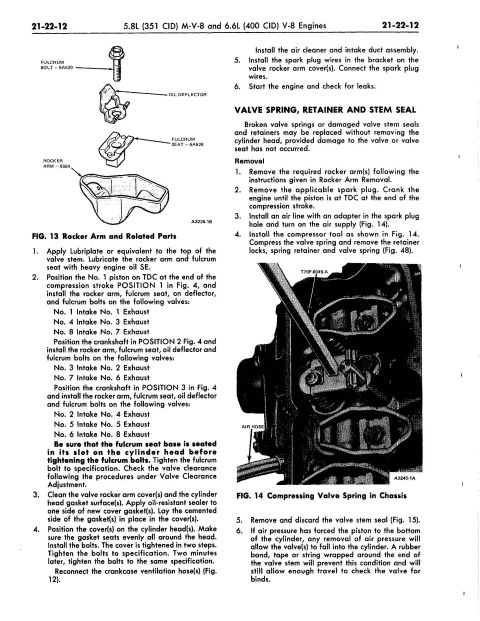
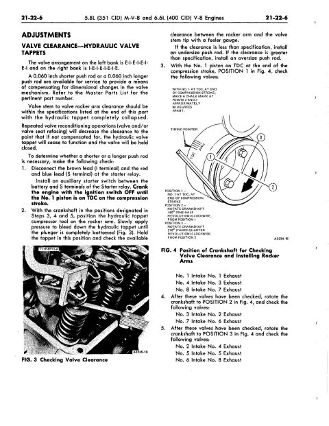
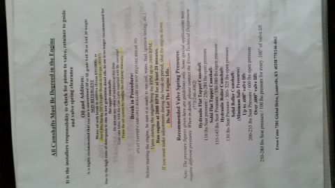
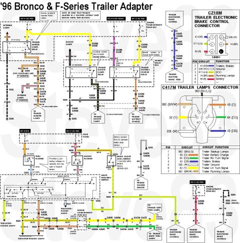
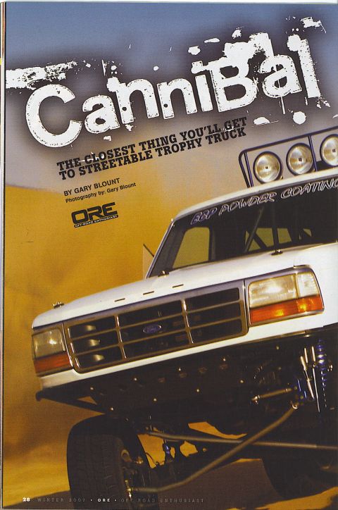
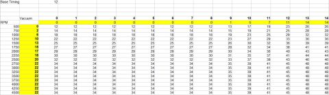
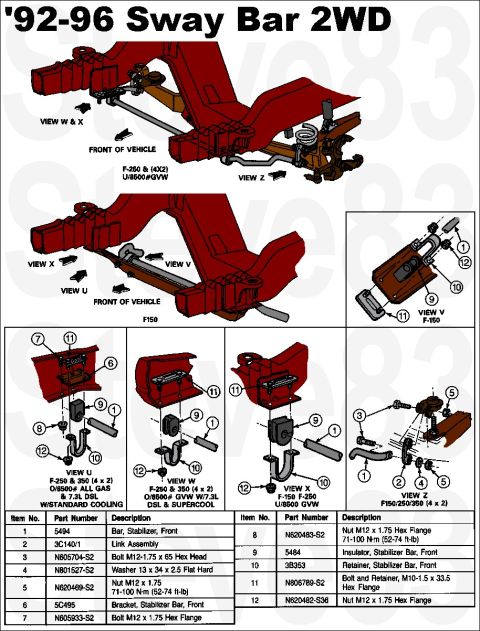
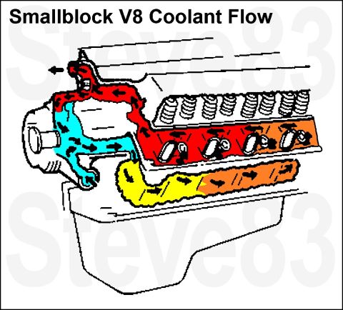
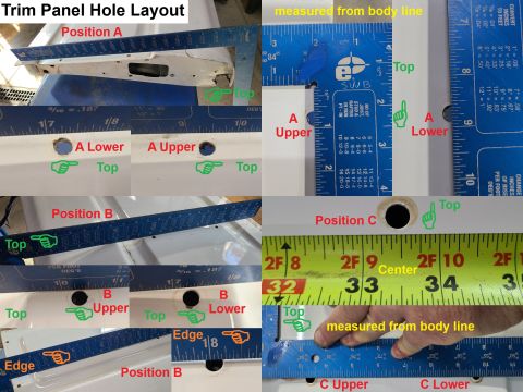
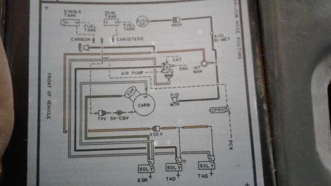
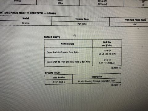
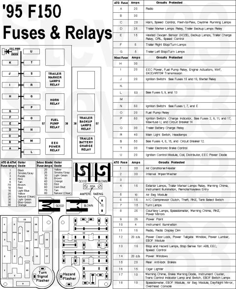
L & L Products engine mount installation instructions, part number 03-0495, with driver and passenger side pho L&L Products 429/460 Engine Mount Stands Install Instructions - 1980+ #04-0425 1992 Ford E4OD Transmission Fault Code Diagnosis Chart - DTC List & Symptoms Ford Bronco Sliding Caliper Pin Installation Diagram - Brake Grease & Pin Tabs Ford Door Lock Cylinder Replacement - Clip Removal & Standard DL140T Swap 1991-95 Ford Bronco/F-Series EEC-IV 3-Digit DTC Codes 335-998 (Page 2) 1991-95 Ford Bronco/F-Series EEC-IV 3-Digit DTC Code List & Definitions Ford Camber/Caster Adjuster Cam Rotation Offset Chart - Alignment Bushing Table 2000-2006 Suburban / Yukon XL 3rd Row Bench Seat Bracket Installation Guide Ford 5.8L 351 / 6.6L 400 V8 Rocker Arm & Valve Spring In-Chassis Service Ford 351M / 400 V8 Valve Clearance & Hydraulic Tappet Adjustment Procedure Erson Cams camshaft install sheet with oil, break-in procedure and valve spring pressures 40service procedures1980-1986 Ford Bronco More reference 1996 Ford Bronco & F-Series Trailer Wiring Diagram - 7-Pin Connector PinoutWiring diagram Off Road Enthusiast Cannibal feature opener with white Ford prerunner truck and roof lightsBrochure Ford Bronco Ignition Timing Curve Table - RPM vs Vacuum Advance (12° Base)Spec plate 1992-96 Ford F-150/F-250/F-350 2WD Front Sway Bar Diagram & Part NumbersExploded parts Smallblock V8 Coolant Flow Diagram - Ford Engine Cooling Path SchematicSchematic 1996 Ford Bronco/F-Series Starting System - Section 03-06 ContentsManual page Trim panel hole layout photos for positions A, B and C with tape measure readings from the body lineBlueprint 1985 Ford Bronco Vacuum Hose Routing Diagram - EGR, TAB/TAD Solenoids, CanisterVacuum routing Bronco drive shaft torque limits table and special tool T74P-4635-CTorque spec '95 F150 fuse and relay chart with fuse panel layout, ATC and Maxi fuse amp tablesFuse chart

L & L Products engine mount instructions for part 03-0495: torque mounts to 50-55 ft. lbs. and drop studs through the existing perch slots.

Part of 1980-1986 Ford Bronco Service Procedures

AI caption · Photo 31 of 129

Italian. Flu: Mwan waav approval 5. in. an: amp" sat. - uu your wands! J emmm ormln-I o 1. Unbun stuck ham. knotli l, I l unin- lrolI 0| Inna! and d "in. who 5 him!!! chMu- d1) am: Ii.- v, Photo a U'L the v. Drivers Sxde Mount ym a: shun." an "as! dwgrili 5. Bun eanlnn' momma to 4291460 on: nan..- yrrl:nu5 7 LVN :I Inska" L & L mounts quua engum mounls [u 5|: h. n. drop thru existing par. mm: u so m " lu. r :lLIUnD: ch lwop nla In clnan

Is this accurate? Sign in to help verify it.
Comments

No comments yet.

More 1980-1986 Broncos