Ford Probe Halo Ring Headlight Wiring Diagram - H4 Harness & Side Marker Tap

Reference · 1993-1997 ProbeAll 66 wiring diagrams
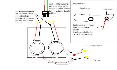
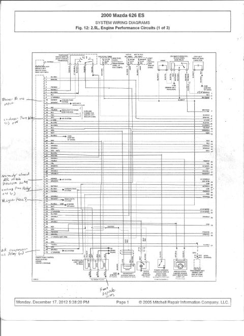
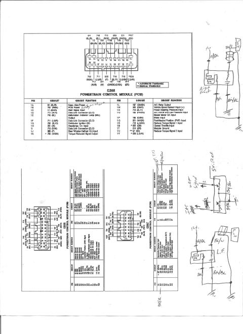
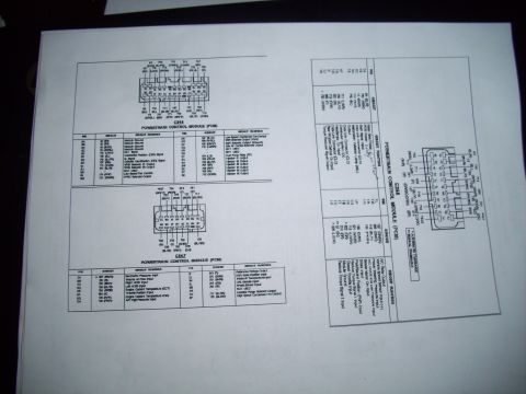
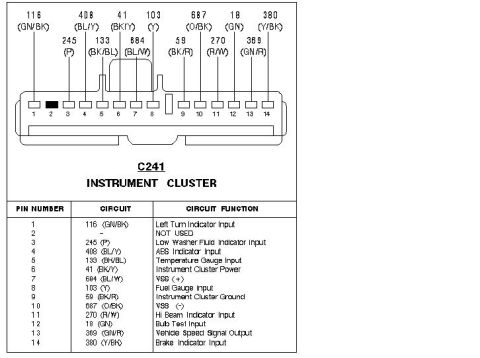
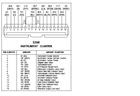
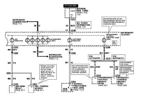
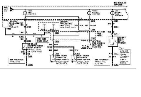
Hand-drawn wiring diagram showing dual-headlight high/low-beam connections and side-marker/signal taps with color-coded wires and handwritten notes.
Part of 1993-1997 Ford Probe Wiring Diagrams
This is a hand-drawn wiring diagram (created in a basic image editor) showing how to wire aftermarket headlights with halo rings ('Rings') to a vehicle's stock or H4 headlight harness. The main drawing shows two round headlight units labeled 'Hi- or low beam' inside a housing, connected via red (positive) and black (ground) wires to a 3-wire stock/H4 connector. The author notes uncertainty about the stock harness wire functions, stating only that BLK (black) = negative/ground and the other two wires are high and low beam. Ground instructions say to connect both male ends into the ground female end on the stock harness, or tap one to the other and connect only one. An inset labeled 'Signal corners' shows a corner lamp assembly with a 'Signal marker' and 'side marker' bulb location, with instructions to tap the positive (+) wires of the rings to the side marker circuit; the author notes running the wire behind the fender to the headlights. Yellow blocks in the drawing represent connection/tap points, with callouts '+ Tap to side marker' and '- ground'. The document contains no part numbers, fuse data, year, make, or model information, it is a general installation sketch for halo-ring headlight wiring.
Is this accurate? Sign in to help verify it.
Frequently asked questions
- Which wire on the stock/H4 headlight harness is ground?
- According to the diagram, the BLK (black) wire is negative/ground; the other two wires are high and low beam (the author was unsure which is which on the stock harness).
- Where do the halo rings get their power?
- The diagram says to tap the positive (+) wires of the rings to the side marker wire in the signal corner assembly, and the author ran the wire behind the fender to the headlights.
- How are the grounds connected for the headlights?
- Connect both male ends into the ground female end on the stock harness, or tap one to the other and connect only one.
- What lights are shown in the main drawing?
- Two round lamps, each labeled 'Hi- or low beam', wired with red (positive, tapped to the side marker) and black (ground) wires.
No comments yet.