Home/
Registry/
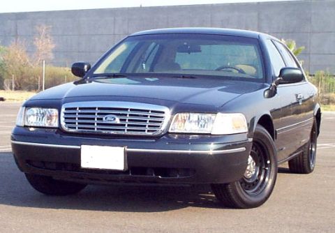
Ford/
Crown Victoria/
1998-2011/
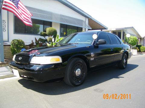
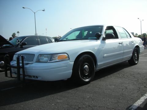
“White Lightning”/
Photo
supermotors.net/registry/media/454162
2006 Crown Victoria C3043 Connector Pinout - Occupant Classification Sensor
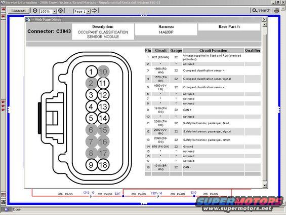
Wiring connector pinout diagram for connector C3043 listing pin numbers, wire colors, gauges, and circuit functions.
This document is a screenshot from Ford Service Information for the 2006 Crown Victoria/Grand Marquis, Supplemental Restraint System section (46-1). It shows the complete pinout for connector C3043, which mates to the Occupant Classification Sensor Module on harness 14A699P. A connector-face illustration depicts the 18-cavity connector, with unused cavities (2, 6, 7, 8, 10, 15, 16, 17) shaded. The accompanying table lists each pin's circuit number, wire color, gauge (all populated circuits are 22 gauge), and function: pin 1 is circuit 937 (RD-WH) voltage supplied in Start and Run; pins 3, 4, and 5 carry the occupant classification sensor +, signal, and - (circuits 1568, 1570, 1569); pins 9 and 18 are CAN + and CAN - (1919 PK-OG and 1918 BR-WH); pins 11-13 serve the passenger safety belt sensor feed, signal, and return (2088, 2089, 2090); and pin 14 is ground on circuit 676 (PK-OG). A wiring segment at the bottom traces the 676 PK-OG ground circuit through connectors C312-10 and C237-16 and splices S217 and S210 to ground point G201. This is useful for diagnosing airbag/OCS and passenger seat belt sensor circuits.
This document covers 2006, which may differ from this 2003 Ford Crown Victoria.
Is this accurate? Sign in to help verify it.
Frequently asked questions
- What does connector C3043 connect to on the 2006 Crown Victoria/Grand Marquis?
- C3043 is the connector for the Occupant Classification Sensor Module, on harness 14A699P, part of the Supplemental Restraint System.
- Which pins on C3043 carry the occupant classification sensor circuits?
- Pin 3 is circuit 1568 (RD-WH) sensor +, pin 4 is circuit 1570 (TN-BK) sensor signal, and pin 5 is circuit 1569 (GY-LB) sensor -. All are 22 gauge.
- Which pins are the CAN bus wires on C3043?
- Pin 9 is CAN + on circuit 1919 (PK-OG) and pin 18 is CAN - on circuit 1918 (BR-WH), both 22 gauge.
- Where does the ground circuit for the Occupant Classification Sensor Module go?
- Pin 14 uses circuit 676 (PK-OG), which routes through C312-10, splice S217, C237-16, and splice S210 to ground point G201.
- Which pins on C3043 are not used?
- Pins 2, 6, 7, 8, 10, 15, 16, and 17 are marked 'not used'.
Comments
More from this build




No comments yet.