Home/
Registry/
Ford/
Bronco/
1980-1986/
“Still Pending”/
Photo
supermotors.net/registry/media/825039
Carter YFA 1-V Carburetor Exploded View Diagram - Ford Bronco Parts Breakdown
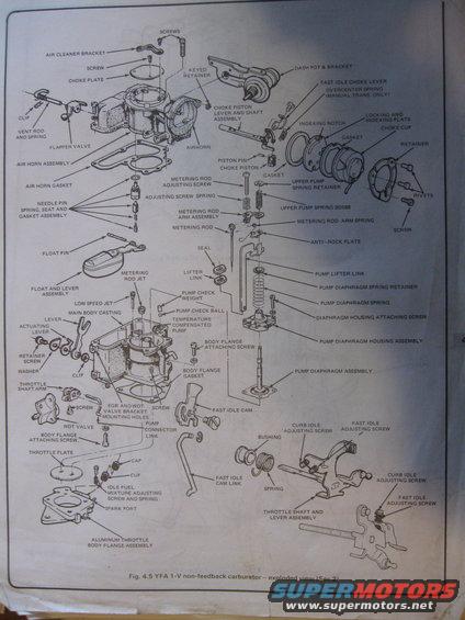
Exploded parts diagram of a YFA 1-V non-feedback carburetor with every component labeled by name.
This document is a labeled exploded-view illustration (Fig. 4.5) of a YFA 1-V non-feedback carburetor, from Section 2 of a service manual. It identifies every major component of the single-venturi carburetor and its relative assembly position, including the air horn assembly with choke plate, vent rod and spring, flapper valve, and air horn gasket; the choke system (choke piston, piston pin, choke piston lever and shaft assembly, choke cup, locking and indexing plate, gasket, retainer, rivets); the fuel metering system (needle pin/spring/seat and gasket assembly, float and lever assembly, float pin, metering rod, metering rod jet, metering rod arm assembly and spring, adjusting screw, low speed jet); the accelerator pump system (temperature compensated pump, pump check ball and weight, pump lifter link, pump diaphragm spring, retainer, diaphragm housing assembly, upper pump spring 9D598); and the throttle body components (main body casting, aluminum throttle body flange assembly, throttle plate, throttle shaft and lever assembly, fast idle cam and link, curb idle and fast idle adjusting screws, idle fuel mixture adjusting screw and spring, WOT valve, spark port, EGR and WOT valve bracket mounting holes). It also shows the dash pot and bracket and notes the overcenter spring is for manual transmission only. Useful for carburetor disassembly, rebuild, and reassembly reference.
Is this accurate? Sign in to help verify it.
Frequently asked questions
- What carburetor does this exploded view diagram show?
- It shows the YFA 1-V non-feedback carburetor (Fig. 4.5, Section 2), with all components labeled in an exploded view.
- Which component is used only on manual transmission models?
- The overcenter spring on the fast idle choke lever is labeled 'MANUAL TRANS. ONLY'.
- What idle adjustment screws are identified on the YFA carburetor?
- The diagram labels the curb idle adjusting screw, fast idle adjusting screw, and the idle fuel mixture adjusting screw and spring.
- What part number is shown for the upper pump spring?
- The upper pump spring is labeled with part number 9D598.
- What accelerator pump parts are shown in the diagram?
- It shows the temperature compensated pump, pump check weight, pump check ball, pump connector link, pump lifter link, pump diaphragm spring and retainer, pump diaphragm assembly, pump diaphragm housing assembly, and diaphragm housing attaching screw.
Comments
More from this build












No comments yet.