Home/
Registry/
Ford/
Bronco/
1980-1986/
“Still Pending”/
Photo
supermotors.net/registry/media/825042
Motorcraft 2150 2-V Carburetor Exploded View Diagram - V6 & V8 Engines
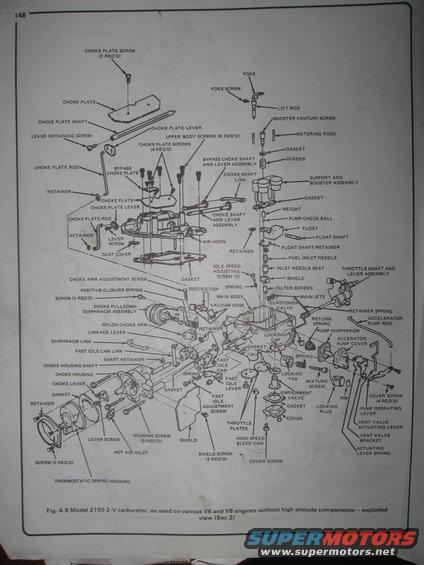
Exploded view of the Motorcraft 2150 2-V carburetor (no high-altitude compensator) labeling choke plate, booster venturi, float, accelerator pump and enrichment valve parts.
This document is page 148 of a repair manual showing an exploded parts diagram of the Model 2150 2-V (two-venturi) carburetor, labeled 'Fig. 4.9' and noted as used on various V6 and V8 engines without a high altitude compensator (Section 2). The illustration breaks the carburetor down into its individual components with callout labels for every part, including the choke plate assembly (choke plate, shaft, lever, rod, screws, retainers), the air horn and upper body screws, the booster venturi with yoke, lift rod, metering rods, support and booster assembly, float system (float, float shaft, retainer, fuel inlet needle, inlet needle seat, filter screen), main body components (main jets, elastomer valve, enrichment valve), accelerator pump parts (pump diaphragm, pump cover, pump rod, return spring, pump check ball, weight), choke pulldown diaphragm assembly, fast idle cam and linkage, choke housing with thermostatic spring housing, throttle shaft and lever assembly, throttle plates, mixture screws, idle speed adjusting screws, vent valve components, and associated gaskets, springs, and fasteners with required quantities (e.g., choke plate screws 4 req'd, upper body screws 6 req'd). A reader can learn the names, relative positions, and assembly order of all 2150 carburetor parts, useful when disassembling, rebuilding, or reassembling this carburetor.
Is this accurate? Sign in to help verify it.
Frequently asked questions
- What carburetor does this exploded diagram show?
- It shows the Model 2150 2-V carburetor, as used on various V6 and V8 engines without a high altitude compensator (Fig. 4.9, Sec 2).
- How many upper body screws does the 2150 carburetor use?
- The diagram calls out 6 upper body screws (6 REQ'D).
- How many choke plate screws are required?
- The top choke plate uses 2 choke plate screws (2 REQ'D); the lower/bypass choke plate section calls out 4 choke plate screws (4 REQ'D).
- What parts make up the fuel inlet/float system in this diagram?
- The float, float shaft, float shaft retainer, fuel inlet needle, inlet needle seat, shield, spring, and filter screen.
- How many housing screws hold the choke housing?
- The diagram shows 3 housing screws (3 REQ'D), plus a thermostatic spring housing retained with 3 screws (3 REQ'D).
Comments
More from this build











No comments yet.