Home/
Registry/
Ford/
Bronco/
1980-1986/
“Still Pending”/
Photo
supermotors.net/registry/media/825040
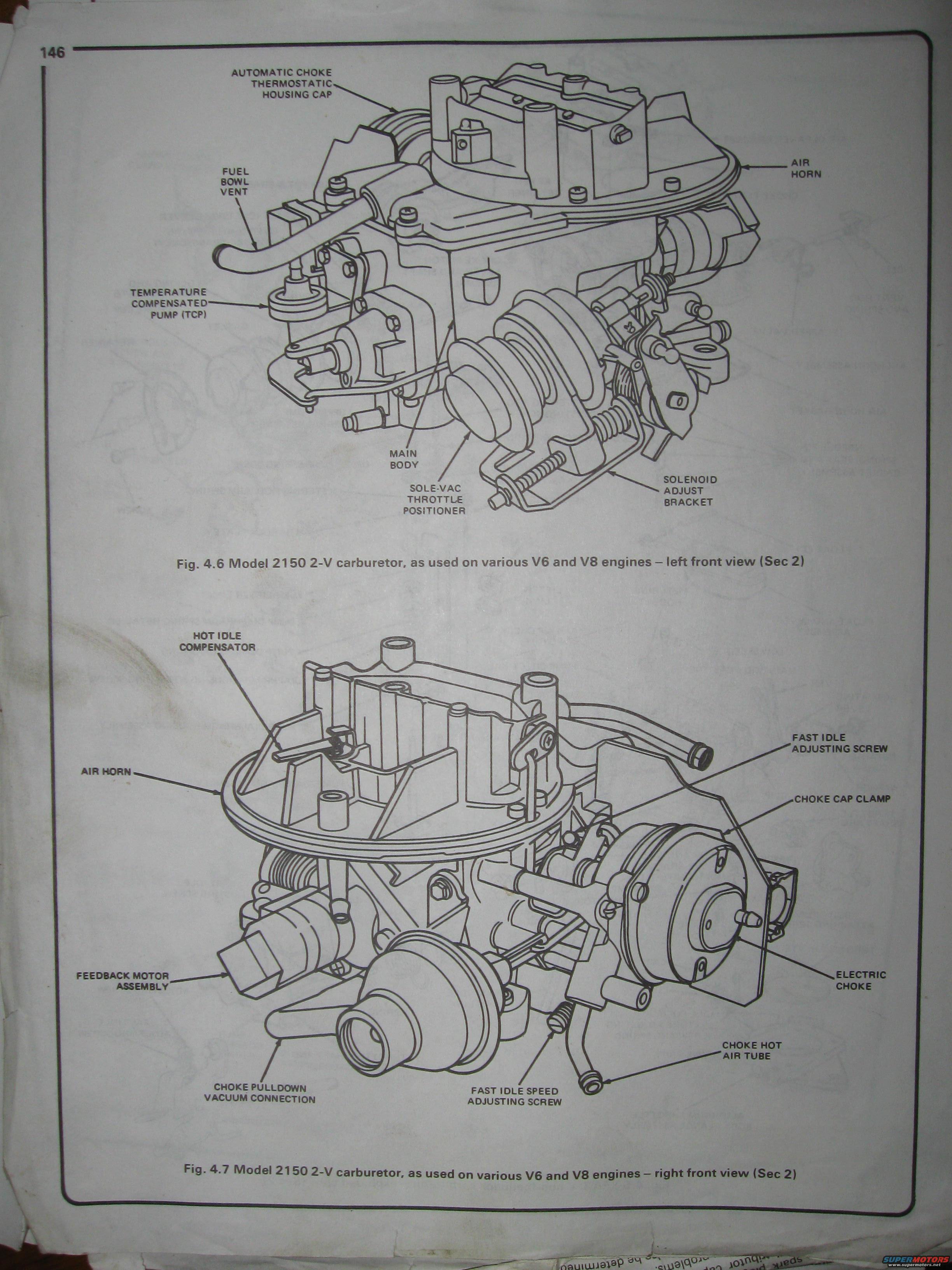
Ford Motorcraft 2150 2-V Carburetor Component Diagram - V6 & V8 Engines
Reference · 1980-1986 BroncoAll 61 exploded parts diagrams
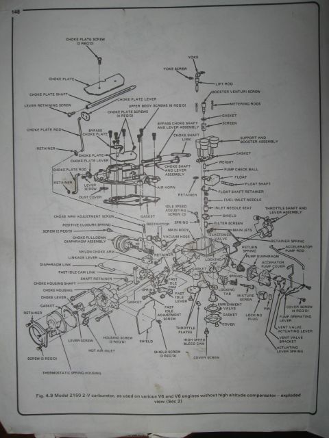
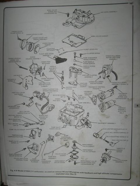
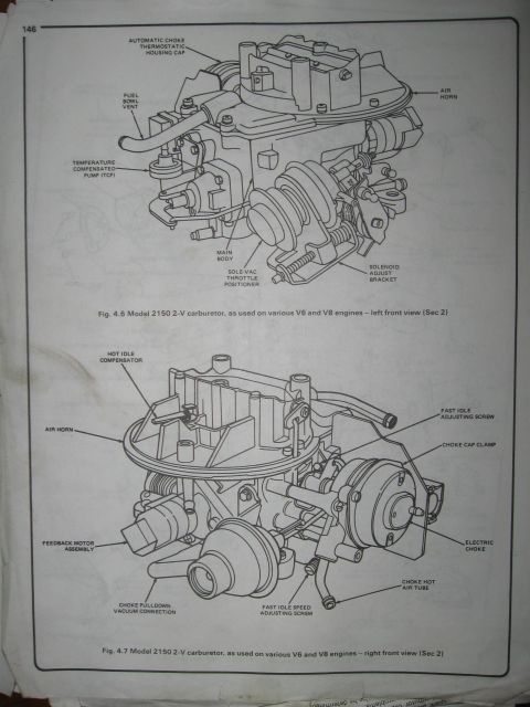
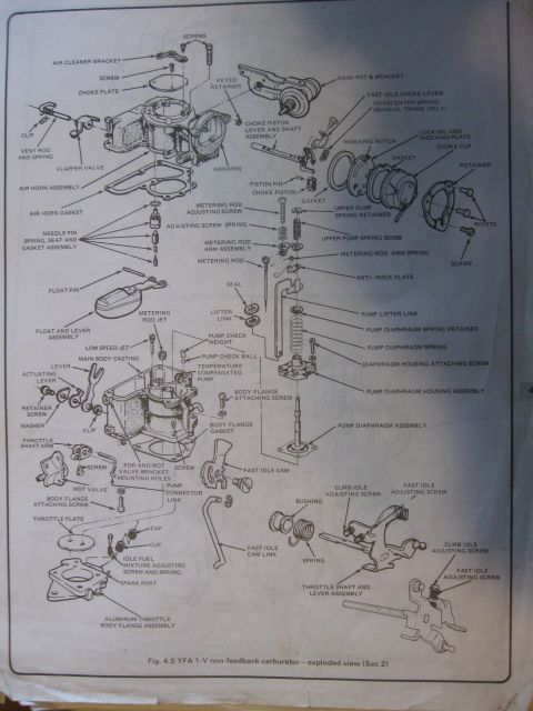
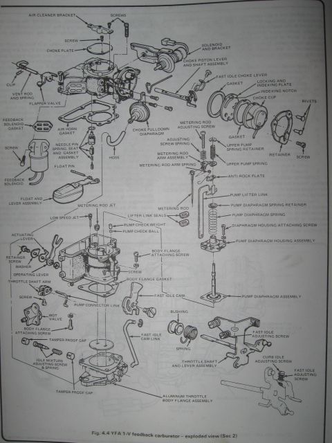
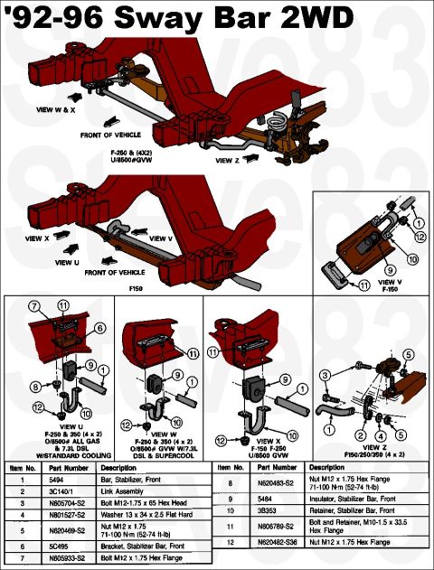
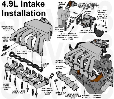
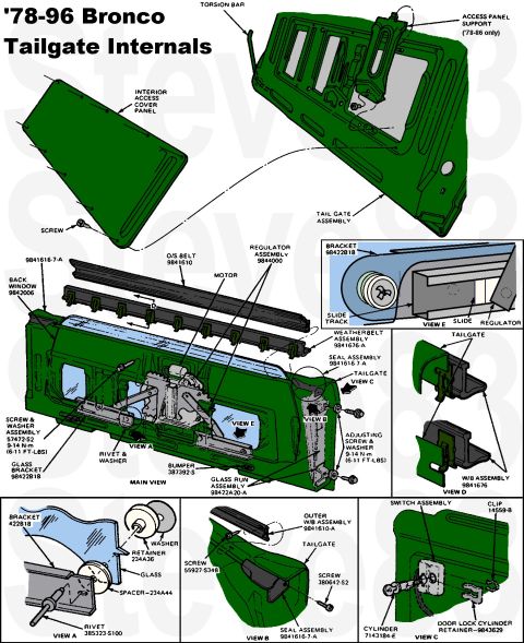

Labeled left- and right-front views of the Motorcraft 2150 2-V carburetor used on V6/V8 engines, identifying choke, feedback motor, TCP and hot idle compensator.
Part of 1980-1986 Ford Bronco Exploded Parts Diagrams
This is page 146 of an automotive repair manual (apparently a Haynes-style manual chapter on fuel/carburetion, Section 2 of Chapter 4). It contains two labeled exploded-view line drawings of the Motorcraft Model 2150 2-V (two-venturi) carburetor, described as used on various V6 and V8 engines. Figure 4.6 shows the carburetor from the left front, identifying the automatic choke thermostatic housing cap, fuel bowl vent, air horn, temperature compensated pump (TCP), main body, Sole-Vac throttle positioner, and solenoid adjust bracket. Figure 4.7 shows the right front view, identifying the hot idle compensator, air horn, fast idle adjusting screw, choke cap clamp, electric choke, feedback motor assembly, choke pulldown vacuum connection, fast idle speed adjusting screw, and choke hot air tube. A reader can use this page to locate and identify the major external components and adjustment points of the 2150 carburetor, such as the fast idle adjusting screws, choke components, and feedback motor, which is useful for tuning, choke service, or carburetor rebuild/identification work. No part numbers, torque specs, or year ranges are stated on the page itself.
Is this accurate? Sign in to help verify it.
Frequently asked questions
- What carburetor model is shown in these diagrams?
- The Model 2150 2-V carburetor, as used on various V6 and V8 engines, shown in left front (Fig. 4.6) and right front (Fig. 4.7) views.
- Where is the fast idle adjusting screw on the 2150 carburetor?
- Fig. 4.7 (right front view) shows both a fast idle adjusting screw near the top right of the carburetor and a fast idle speed adjusting screw lower down near the choke hot air tube.
- What choke components are identified on the 2150 carburetor?
- The automatic choke thermostatic housing cap (Fig. 4.6), and in Fig. 4.7 the choke cap clamp, electric choke, choke pulldown vacuum connection, and choke hot air tube.
- What is the Sole-Vac throttle positioner?
- It is a component labeled on the left front view (Fig. 4.6) of the 2150 carburetor, located on the main body near the solenoid adjust bracket.
- What does TCP stand for on this diagram?
- Temperature Compensated Pump, labeled on the left front view of the carburetor in Fig. 4.6.


No comments yet.