Home/
Registry/
Ford/
Bronco/
1992-1996/
“pukin' dogII”/
Photo
supermotors.net/registry/media/877840
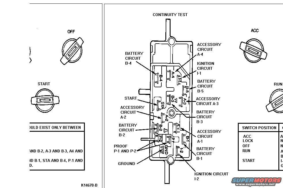
1996 Ford Bronco Ignition Switch Continuity Test Diagram - Terminal Pinout
Reference · 1992-1996 BroncoAll 411 wiring diagrams
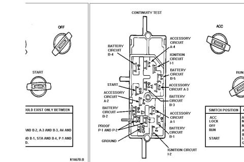













Ignition switch continuity-test diagram showing internal contacts and battery, accessory and ignition circuits by switch position.
Part of 1992-1996 Ford Bronco Wiring Diagrams
This document is an ignition switch continuity test diagram, uploaded to a 1996 Ford Bronco gallery. The central illustration shows the ignition switch connector body with all terminal positions labeled: Battery circuits B-1 through B-5, Accessory circuits A-1 through A-4, Ignition circuits I-1 and I-2, START (STA), PROOF terminals P-1 and P-2, and GROUND (GND). Surrounding the connector are four key-cylinder position illustrations showing the switch in OFF, START, ACC, and RUN positions, indicating that continuity should be checked with the key in each of these positions. Two tables accompany the diagram, one listing which terminal pairs should show continuity (partially cut off, but referencing pairs such as A-3 and B-3, STA and B-4, P-1 and...) and a 'SWITCH POSITION' table listing ACC, LOCK, OFF, RUN, and START positions with their corresponding energized circuits (right column cut off in the scan). The figure carries the identifier K14670-B. A technician can use this diagram to identify each pin of the ignition switch connector and verify correct switch operation with an ohmmeter in each key position.
Is this accurate? Sign in to help verify it.
Frequently asked questions
- What terminals are on the Ford ignition switch connector shown in this diagram?
- The connector includes battery circuits B-1, B-2, B-3, B-4 and B-5; accessory circuits A-1, A-2, A-3 and A-4; ignition circuits I-1 and I-2; the START terminal (STA); proof terminals P-1 and P-2; and a GROUND (GND) terminal.
- Which key positions are used for the ignition switch continuity test?
- The diagram shows the key/switch in OFF, START, ACC and RUN positions, and the accompanying table lists switch positions ACC, LOCK, OFF, RUN and START.
- What is the figure reference number on this diagram?
- The diagram is identified as K14670-B.
- Which terminal pairs are mentioned for continuity in the left table?
- The visible (partially cut-off) portion references pairs including '...AND B-2, A-3 AND B-3, A4 AND...' and '...ND B-1, STA AND B-4, P-1 AND...'. The full pairs are cut off at the page edge.






No comments yet.