Home/
Registry/
Ford/
Probe/
1993-1997/
1993 Ford Probe/
Photo
supermotors.net/registry/media/183357
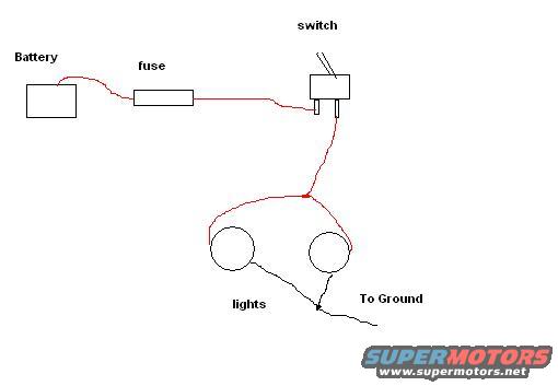
Simple Auxiliary Lights Wiring Diagram - Battery, Fuse, Switch to Lights & Ground
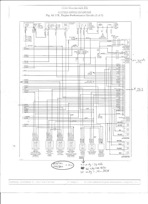
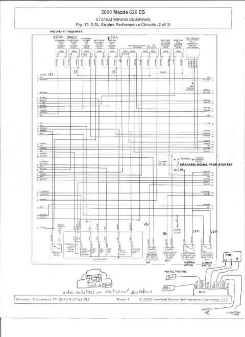
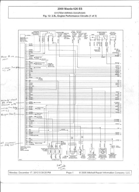
Reference · 1993-1997 ProbeAll 65 wiring diagrams

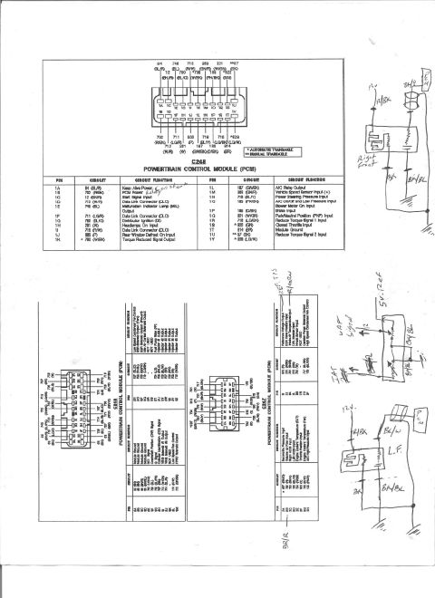
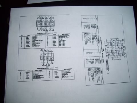
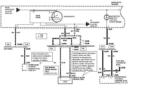
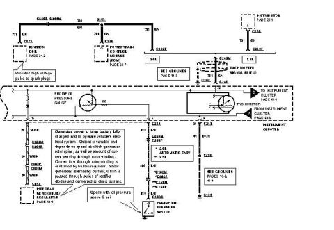

Simple hand-drawn lighting wiring diagram showing battery, fuse, switch, lights, and ground connections.
Part of 1993-1997 Ford Probe Wiring Diagrams
This is a simple hand-drawn (computer-sketched) wiring diagram showing how to wire a basic auxiliary light circuit, uploaded to the gallery of a 1993 Ford Probe. The diagram shows five labeled elements connected in sequence: a Battery, connected by a red (power) wire to an inline fuse, which continues to a switch. From the switch, a single red feed wire runs down and splits at a junction point to feed two round lights wired in parallel. The return side of both lights is joined by a black wire labeled 'To Ground.' The drawing conveys the standard order of components for a fused, switched accessory lighting circuit: battery → fuse → switch → lights → ground. No wire gauges, fuse amperage ratings, relay, part numbers, connector details, or vehicle-specific information are given. It is a generic conceptual schematic rather than a factory diagram, useful as a quick reference for someone installing aftermarket driving lights, fog lights, or similar accessories on any vehicle. Readers can learn the basic circuit topology (fuse placed close to the battery, switch controlling power to both lights, common ground for the lamps) but must determine appropriate fuse size and wire gauge from other sources.
Is this accurate? Sign in to help verify it.
Frequently asked questions
- What components are shown in this lighting wiring diagram?
- It shows a battery, an inline fuse, a switch, two lights, and a ground connection.
- In what order are the components wired?
- Power runs from the battery to the fuse, then to the switch, then splits to feed the two lights, whose return side goes to ground.
- Are the two lights wired in series or parallel?
- The power wire splits at a junction to feed both lights, so they are wired in parallel with a common ground.
- Does the diagram specify a fuse amperage or wire gauge?
- No. The fuse is labeled only as 'fuse' with no amp rating, and no wire gauges are indicated.
- Where is the fuse placed in the circuit?
- The fuse is placed on the power wire between the battery and the switch.
No comments yet.