Simple Home Network Diagram - ADSL Modem, Wireless Router, Wired & Wireless PCs
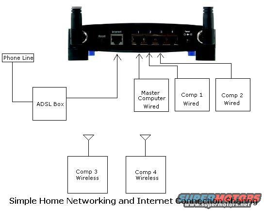
Schematic of a simple home network connecting an ADSL box, router, and wired and wireless computers.
This document is not an automotive schematic; it is a simple home computer networking diagram titled "Simple Home Networking and Internet Connection Sharing." It depicts the rear panel of a wireless router (with two antennas, a Reset button, an Internet/WAN port, four numbered LAN ports labeled 1-4, and a Power connector). The diagram shows a Phone Line feeding into an ADSL Box (modem), which connects to the router's Internet port. Three wired devices, a Master Computer, Comp 1, and Comp 2, connect via cables to the router's numbered LAN ports. Two additional computers, Comp 3 and Comp 4, are shown connecting wirelessly, indicated by antenna symbols. A reader can learn the basic topology for sharing an ADSL internet connection among multiple computers: phone line to ADSL modem, modem to router WAN port, wired PCs to LAN ports, and wireless PCs to the router's Wi-Fi. The document contains no vehicle-related information, no fuse data, wire colors, part numbers, or year/model applicability. Despite being filed in a 1993 Ford Probe gallery, it has no automotive content whatsoever.
Is this accurate? Sign in to help verify it.
Frequently asked questions
- How does the internet connection reach the router in this diagram?
- A Phone Line connects to an ADSL Box, which then connects to the router's Internet port.
- How many computers are wired to the router?
- Three: the Master Computer, Comp 1, and Comp 2 are shown wired to the router's numbered LAN ports.
- Which computers connect wirelessly?
- Comp 3 and Comp 4 are labeled Wireless and are shown with antenna symbols connecting to the router over Wi-Fi.
- What ports are visible on the router's rear panel?
- A Reset button, an Internet port, four numbered LAN ports (1, 2, 3, 4), and a Power connector.
Comments
More from this build






No comments yet.