Ford 300 I6 (6-300) Combination Manifold Tightening Sequence Diagram - Fig. 70

Reference · 1980-1986 BroncoAll 40 service procedures
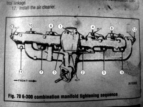






Service figure showing the numbered bolt tightening sequence for a 6-300 combination intake manifold.
Part of 1980-1986 Ford Bronco Service Procedures
This is a scanned page from an automotive service manual showing the tightening sequence for the combination intake/exhaust manifold on the Ford 6-cylinder 300 cubic inch (6-300) engine. The top of the page shows the tail end of an installation procedure, including a partial step referencing linkage and step 17, 'Install the air cleaner.' The main content is Fig. 70, an illustration of the combined intake and exhaust manifold assembly viewed from the side, with numbered callouts 1 through 13 indicating the order in which the manifold fasteners must be tightened. Several fastener positions are specifically labeled 'NUT' (positions 4, 12, 13, and a lower center fastener), distinguishing nuts from bolts in the sequence. A 'FRONT' arrow at the lower left orients the diagram relative to the engine's front. The sequence begins at position 1 near the center of the manifold and works outward in an alternating pattern toward the ends. A reader can use this figure to correctly torque the combination manifold fasteners in the proper order when reinstalling the manifold on a Ford 300 inline six engine, such as those used in Ford trucks and Broncos. No torque values or year applicability are printed on this page.
Is this accurate? Sign in to help verify it.
Frequently asked questions
- What is the tightening sequence for the Ford 6-300 combination manifold?
- Per Fig. 70, tighten the fasteners in numerical order 1 through 13, starting at position 1 near the center of the manifold and alternating outward to positions 12 and 13 at the ends.
- Which fasteners in the sequence are nuts?
- The diagram labels positions 4, 12, and 13 as 'NUT,' plus one lower center fastener near the manifold outlet also labeled 'NUT.'
- How many fasteners are in the 6-300 manifold tightening sequence?
- The diagram shows 13 numbered fastener positions in the tightening sequence.
- What is the final step of the procedure shown before the diagram?
- Step 17 instructs to install the air cleaner.
- Does this document give torque specifications for the manifold?
- No, the visible portion only shows the tightening order (Fig. 70); no torque values are printed on this page.






No comments yet.