Home/
Registry/
Ford/
Probe/
1993-1997/
1994 Ford Probe/
Photo
supermotors.net/registry/media/173236
1994 Ford Probe GT MSD External Coil HEI Module Wiring Diagram
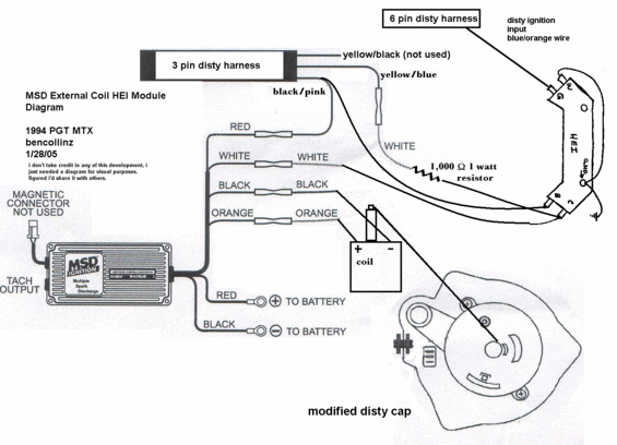
User-drawn MSD external-coil HEI module wiring diagram for a 1994 PGT MTX: tach output black/pink, 1000 ohm 1-watt resistor, RED/BLACK to battery, 6-pin and 3-pin distributor harness colors.
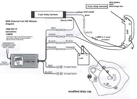
This is a hand-annotated wiring diagram titled "MSD External Coil HEI Module Diagram," drawn by community member "bencollinz" and dated 1/28/05, labeled for a 1994 PGT MTX (Probe GT, manual transmission). It shows how to wire an MSD Multiple Spark Discharge ignition box together with a GM-style HEI module and an external coil onto the factory distributor harnesses. The 3-pin distributor harness supplies a yellow/black wire (not used), a yellow/blue wire, and a black/pink wire; the 6-pin distributor harness provides the disty ignition input on a blue/orange wire routed to the HEI module. The MSD box's RED, WHITE, BLACK, and ORANGE leads are spliced through inline connectors: the WHITE wire passes through a 1,000-ohm 1-watt resistor path to the HEI module, and the BLACK and ORANGE leads connect to the external coil's + and − terminals. The MSD's heavy RED and BLACK power leads go directly to the battery positive and negative terminals, the magnetic pickup connector is not used, and a tach output is available on the MSD box. The HEI module terminals are labeled W, G, B, C, and GND, and a sketch of a "modified disty cap" (distributor cap) is included. The author notes the diagram is for visual purposes only.
Is this accurate? Sign in to help verify it.
Frequently asked questions
- What vehicle is this MSD external coil HEI wiring diagram for?
- The diagram is labeled "1994 PGT MTX" (Probe GT, manual transmission), drawn by bencollinz and dated 1/28/05.
- Which distributor harness wire is not used in this MSD/HEI conversion?
- The yellow/black wire from the 3-pin disty harness is marked "not used," and the MSD's magnetic connector is also not used.
- What resistor is required in this wiring setup?
- A 1,000 Ω (ohm) 1-watt resistor is shown inline on the white wire path to the HEI module.
- Where do the MSD box's heavy red and black wires connect?
- The RED wire goes to the battery positive (+) terminal and the BLACK wire goes to the battery negative (−) terminal.
- Which wire carries the distributor ignition input to the HEI module?
- The blue/orange wire from the 6-pin disty harness is labeled as the disty ignition input.
Comments
More from this build



No comments yet.