Home/
Registry/
Ford/
Probe/
1993-1997/
1994 Ford Probe/
Photo
supermotors.net/registry/media/178174
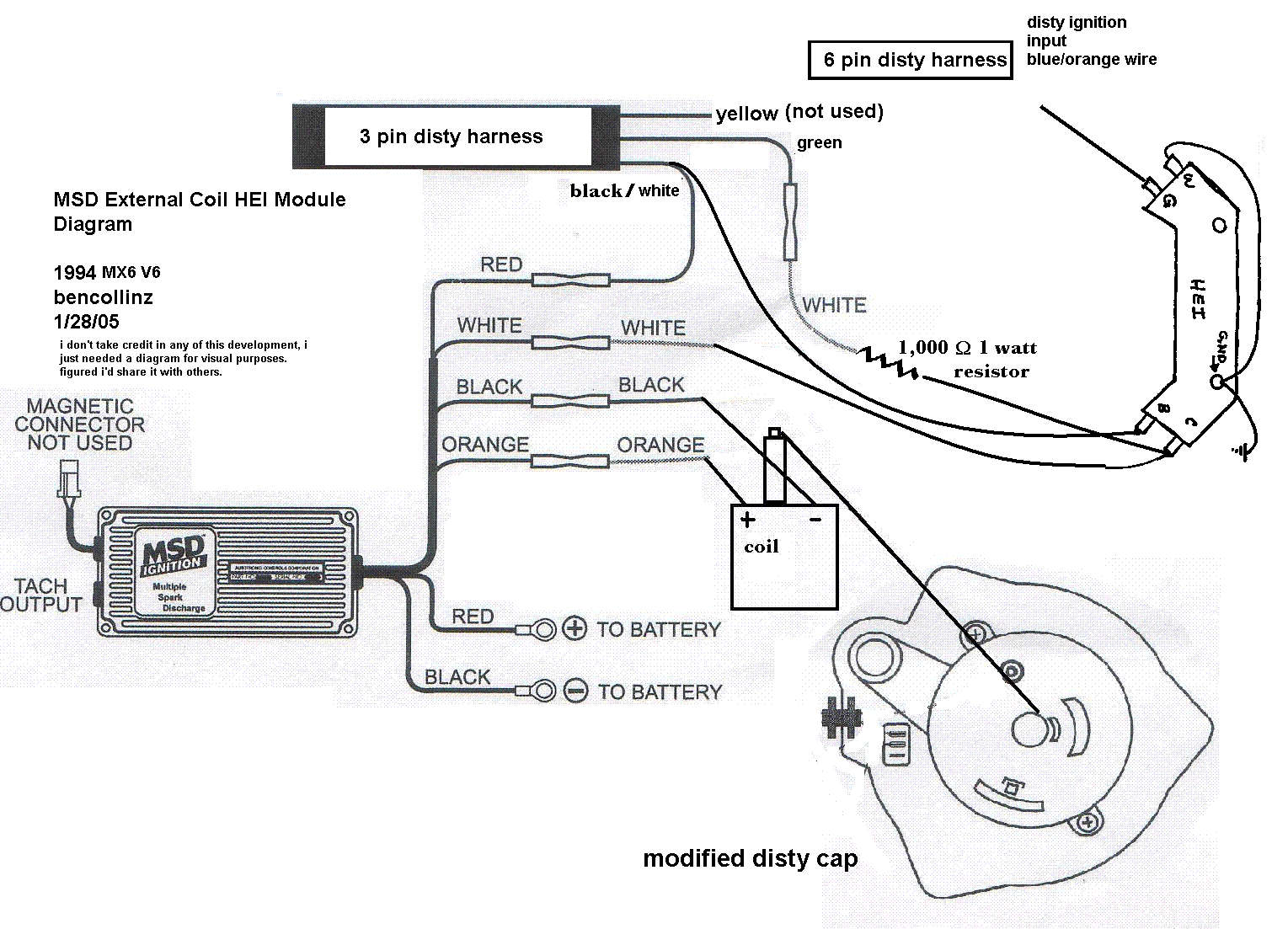
MSD External Coil HEI Module Wiring Diagram - 1994 MX6 V6 Distributor Ignition
Reference · 1993-1997 ProbeAll 65 wiring diagrams
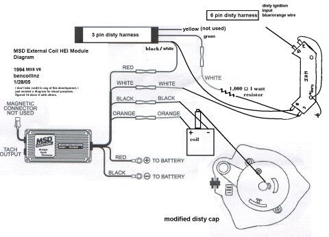
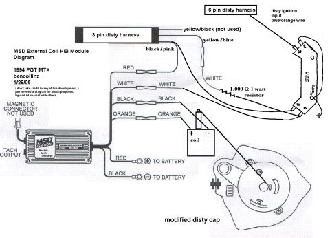

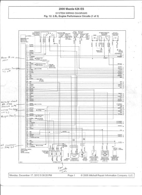
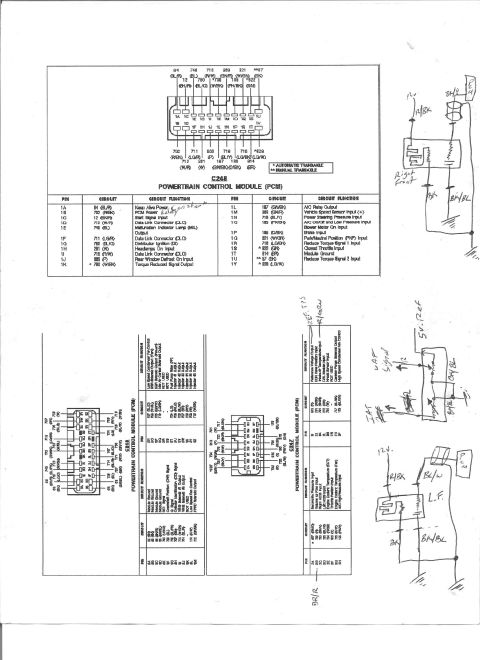
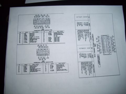
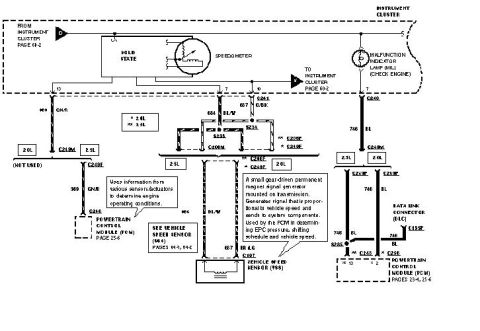





User-drawn MSD external-coil HEI module wiring diagram for a 1994 MX6 V6: tach output black/white, 1000 ohm 1-watt resistor, RED/BLACK to battery, 6-pin and 3-pin distributor harness colors.
Part of 1993-1997 Ford Probe Wiring Diagrams
This is a hand-annotated wiring diagram titled "MSD External Coil HEI Module Diagram," created by user "bencollinz" on 1/28/05 for a 1994 MX6 V6. It shows how to wire an MSD Multiple Spark Discharge ignition box together with a GM-style HEI module and an external ignition coil to the vehicle's distributor harnesses. The factory 3-pin distributor harness wires are identified: yellow (not used), green, and black/white. A separate 6-pin distributor harness carries the distributor ignition input on the blue/orange wire. The MSD box's red, white, black, and orange wires are shown connecting through inline splices, with the white circuit passing through a 1,000-ohm 1-watt resistor to the HEI module, whose terminals (W, G, B, C, GND) are labeled. The MSD's heavy red and black leads go directly to the battery positive and negative terminals, and the tach output terminal is called out; the magnetic pickup connector is not used. The coil's + and − terminals are shown, and a sketch of a "modified disty cap" (distributor cap) illustrates where connections route into the distributor. The author notes the diagram was made purely for visual reference and shared for others' benefit.
Is this accurate? Sign in to help verify it.
Frequently asked questions
- What vehicle is this MSD HEI external coil wiring diagram for?
- The diagram is labeled for a 1994 MX6 V6, drawn by user bencollinz on 1/28/05.
- Which wire on the 3-pin distributor harness is not used?
- The yellow wire on the 3-pin disty harness is marked 'not used'. The other wires are green and black/white.
- What resistor is required in this MSD/HEI conversion?
- A 1,000 Ω (1,000 ohm) 1 watt resistor is placed in the white wire circuit going to the HEI module.
- Where do the MSD box's main red and black wires connect?
- The heavy red wire goes to the battery positive (+) terminal and the heavy black wire goes to the battery negative (−) terminal.
- Where does the distributor ignition input come from on the 6-pin harness?
- The disty ignition input is on the blue/orange wire of the 6-pin disty harness.






No comments yet.