SuperMotors SuperMotors SUPERMOTORS Search: try “orange Bronco on 35s”
Home/ Registry/ Ford/ Probe/ 1993-1997/ “SE”/ Photo supermotors.net/registry/media/210538

1994 Ford Probe Intake Manifold Sketch - Long & Short Runner Ports, Throttle Body

Hand-drawn sketch of an intake manifold with labeled long/short runners
Hand-drawn sketch of an intake manifold with labeled long/short runnersOriginal file
Hand-drawn sketch of an intake manifold with labeled long/short runners

Reference · 1993-1997 ProbeAll 25 schematics

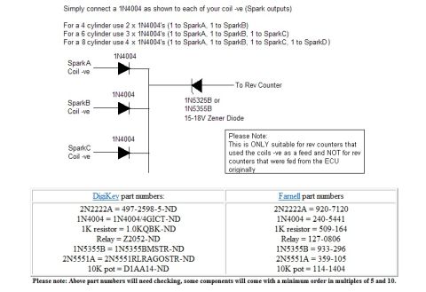
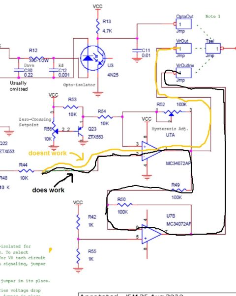
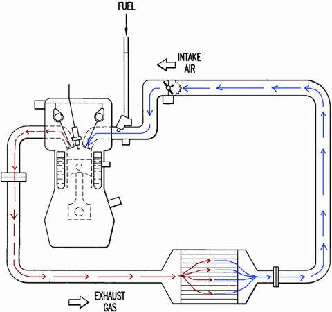
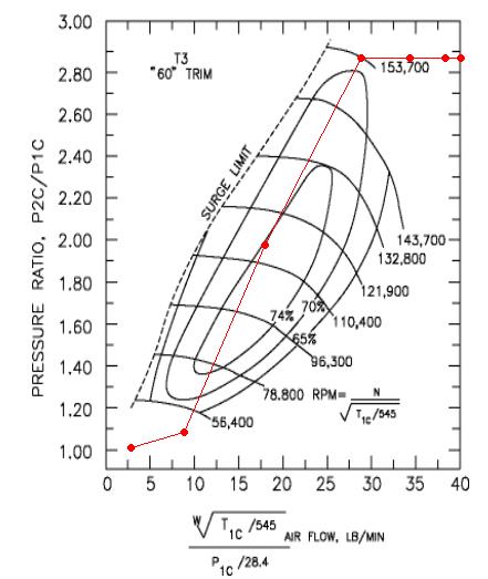
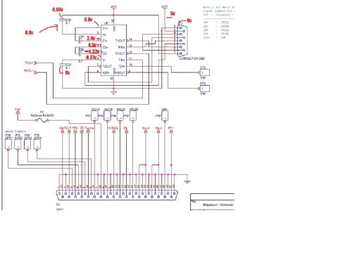
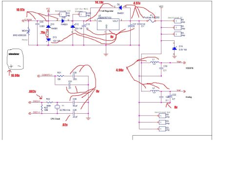
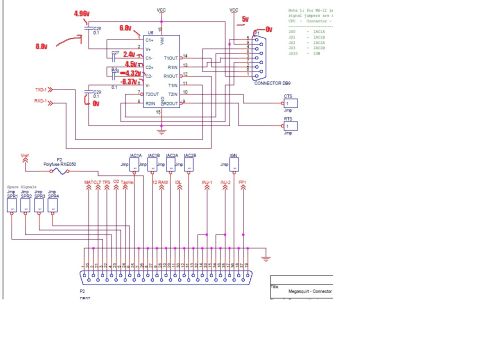
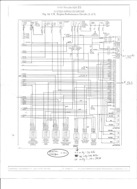
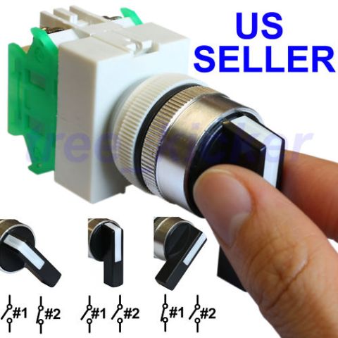
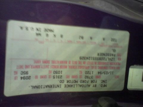
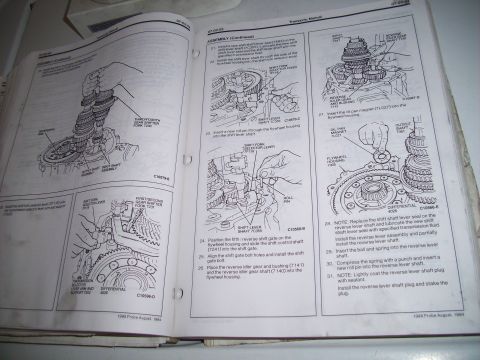
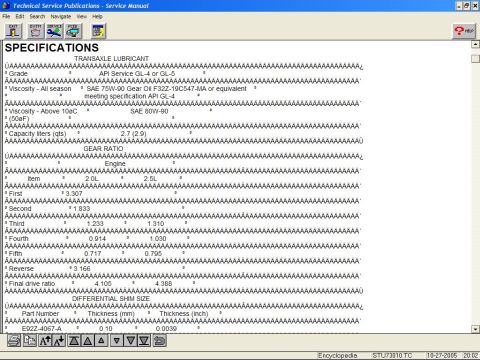
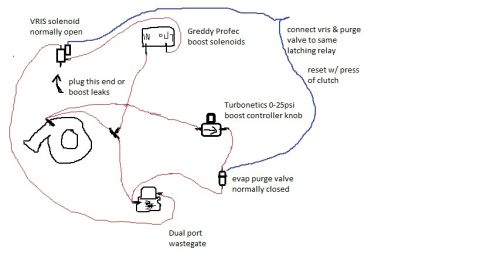
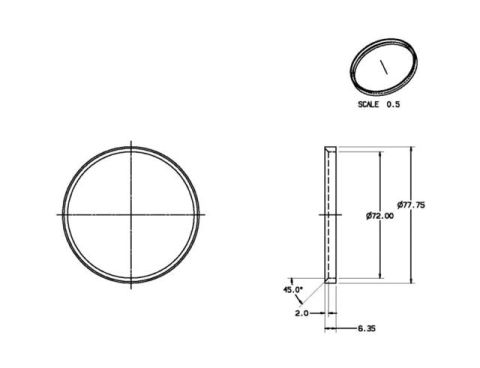
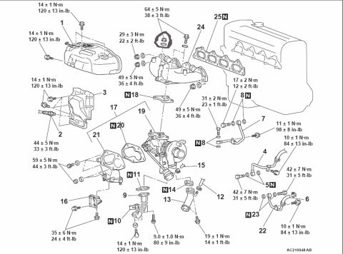
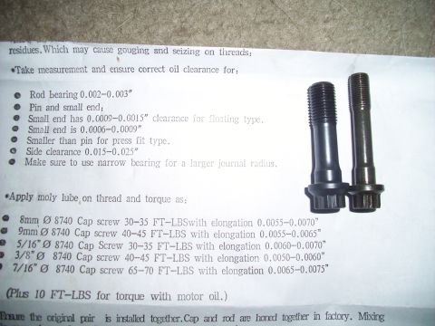
1994 Ford Probe Intake Manifold Sketch - Long & Short Runner Ports, Throttle Body Tachometer Output from Coil Negative - 1N4004 Diode Rev Counter Schematic MegaSquirt MS2 VR/Tach Input Circuit Schematic - 4N25 Opto & MC34072AP Debug Exhaust Venturi Turbo Flow Schematic - Intake Air, Fuel & Exhaust Gas Diagram Garrett T3 60 Trim Turbo Compressor Map with Plotted Operating Line Ford Probe ECU Board U6 MAX232-Type IC Pin Voltages - Good Board Reference U6 Chip Serial Interface Schematic & Test Voltages - Shorted Board Diagnosis 68HC908GP32 Microcontroller Pinout with 5V & GND Annotations - Ford Probe Schematic MegaSquirt II Power Supply & CPU Clock Schematic with Voltage Test Readings MegaSquirt DB37 & DB9 Connector Schematic - Pinout, Jumpers & Test Voltages Megasquirt MSII Power Supply Schematic - LM2937ET-5.0 5V Regulator & CPU Clock MegaSquirt DB37 Connector & DB9 Serial Schematic with U6 Voltage Test Points 25schematics1993-1997 Ford Probe More reference 2000 Mazda 626 2.5L Engine Performance Wiring Diagram - PCM Pins & O2 SensorsWiring diagram 3-Position Rotary Selector Switch: Contact Positions #1 & #2 DiagramBrochure AutoAlliance International vehicle certification label dated 11/23/94 with GVWR and GAWR ratingsSpec plate 1995 Probe manual transaxle assembly procedure pages with shift lever and reverse lever stepsService procedure Manual transaxle specifications screen with lubricant grade, 2.0L and 2.5L gear ratios and differential shim sManual page 1995 Ford Probe Multi-Stage Boost Control Vacuum Routing Diagram - Wastegate SetupVacuum routing Hub Spacer Ring Blueprint - Ø77.75 OD x Ø72.00 ID x 6.35 Thick (Ford Probe)Blueprint Exhaust Manifold & Turbocharger Exploded Diagram with Torque Specs (AC210648AB)Exploded parts Connecting Rod Bolt Torque Specs & Clearances - 8740 Cap Screw Instruction SheetTorque spec

Hand-drawn schematic of an intake manifold showing long and short intake runner ports and throttle body location.

Part of 1993-1997 Ford Probe Schematics

AI caption · Photo 10 of 28

This document is a hand-drawn pencil sketch (schematic-style illustration) of an automotive intake manifold, uploaded as "intake.jpg" to a 1994 Ford Probe gallery. The drawing shows a multi-runner intake manifold in side/perspective view, sitting atop what appears to be a cylinder head and engine block outline. Three callout labels identify key features: the "LONG INTAKE RUNNER PORT" (pointing to the upper set of long, curved runners), the "SHORT INTK. RUN. PORT" (pointing to a shorter runner path near the plenum), and the "THROTTLEBODY" mounting flange at the right side of the manifold, drawn as a circular opening with an angled shaft/linkage. The sketch illustrates a variable-length or dual-runner intake design in which air can travel through either long or short runner paths before reaching the intake ports. The drawing is credited "By: KL_Ottawa." No year, make, model, engine designation, part numbers, dimensions, or torque values appear anywhere in the document; it is purely a conceptual/illustrative diagram of intake runner routing and the throttle body location. Readers can learn the general layout and relationship of the long runners, short runners, and throttle body on this manifold design.

Is this accurate? Sign in to help verify it.

Frequently asked questions

What does this diagram show?
A hand-drawn sketch of an intake manifold, labeling the long intake runner port, the short intake runner port, and the throttle body location.
Where is the throttle body located on this manifold?
The throttle body flange is drawn at the right-hand end of the manifold, shown as a circular opening with an angled shaft.
Does the manifold have more than one runner length?
Yes, the drawing labels both a long intake runner port and a short intake runner port, indicating two runner paths.
Who created this drawing?
It is credited "By: KL_Ottawa."

Comments

No comments yet.

More 1993-1997 Probes