Home/
Registry/
Ford/
Probe/
1993-1997/
1994 Ford Probe/
Photo
supermotors.net/registry/media/307592
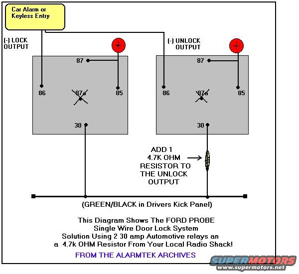
Ford Probe Door Lock Wiring Diagram - Single Wire Relay & Resistor Alarm Hookup
Reference · 1993-1997 ProbeAll 65 wiring diagrams
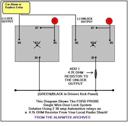

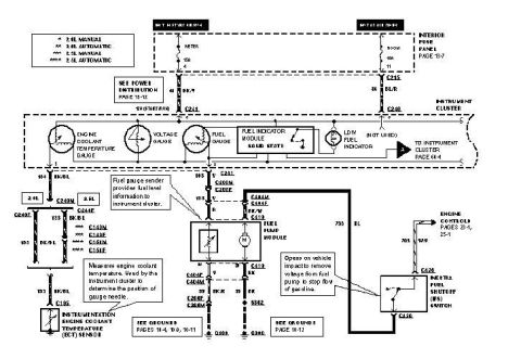
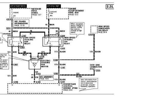
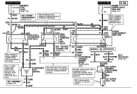
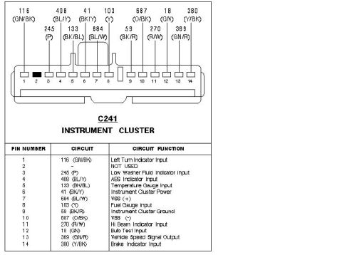





Alarm/keyless-entry door-lock interface for Ford Probe single-wire lock system: two 30A automotive relays with a 4.7k ohm resistor added to the unlock output (Green/Black wire in driver kick panel).
Part of 1993-1997 Ford Probe Wiring Diagrams
This wiring diagram from the Alarmtek Archives shows how to interface a car alarm or keyless entry system with the Ford Probe's single-wire door lock system. The diagram depicts two standard 30-amp automotive relays (with pins labeled 87, 87a, 86, 85, and 30). The negative (-) LOCK output from the alarm/keyless entry unit triggers one relay via pin 86, and the negative (-) UNLOCK output triggers the second relay via pin 86. Pin 85 of each relay connects to a positive power source (shown as red +12V symbols), along with pin 87. Pin 30 of both relays connects to the GREEN/BLACK wire located in the driver's kick panel. Critically, a 4.7K ohm resistor must be added in-line on the unlock relay's pin 30 output before it joins the GREEN/BLACK wire. This resistor arrangement allows a single wire to carry both lock and unlock signals to the Probe's door lock control circuit, distinguished by resistance. The diagram notes that the relays and resistor can be sourced from Radio Shack. This is useful for anyone installing an aftermarket alarm or keyless entry system with power door lock control on a Ford Probe.
Is this accurate? Sign in to help verify it.
Frequently asked questions
- What wire controls the door locks on a Ford Probe and where is it located?
- The GREEN/BLACK wire, located in the driver's kick panel, is the single wire for the door lock system.
- What resistor is needed to add keyless entry to the Ford Probe door locks?
- A 4.7K ohm resistor must be added to the unlock output (on pin 30 of the unlock relay) before it connects to the GREEN/BLACK wire.
- What relays are needed for this Ford Probe door lock interface?
- Two 30 amp automotive relays are used, one triggered by the (-) lock output and one by the (-) unlock output of the alarm or keyless entry system. The diagram notes they can be bought from Radio Shack.
- How are the relays wired to the alarm outputs?
- The alarm/keyless entry (-) lock output goes to pin 86 of one relay and the (-) unlock output goes to pin 86 of the second relay. Pins 85 and 87 connect to +12V, and pin 30 of each relay connects to the GREEN/BLACK wire (with a 4.7K ohm resistor inline on the unlock relay's pin 30).






No comments yet.