Home/
Registry/
Ford/
Probe/
1993-1997/
“spideys oposite (GFs PGT)”/
Photo
supermotors.net/registry/media/310990
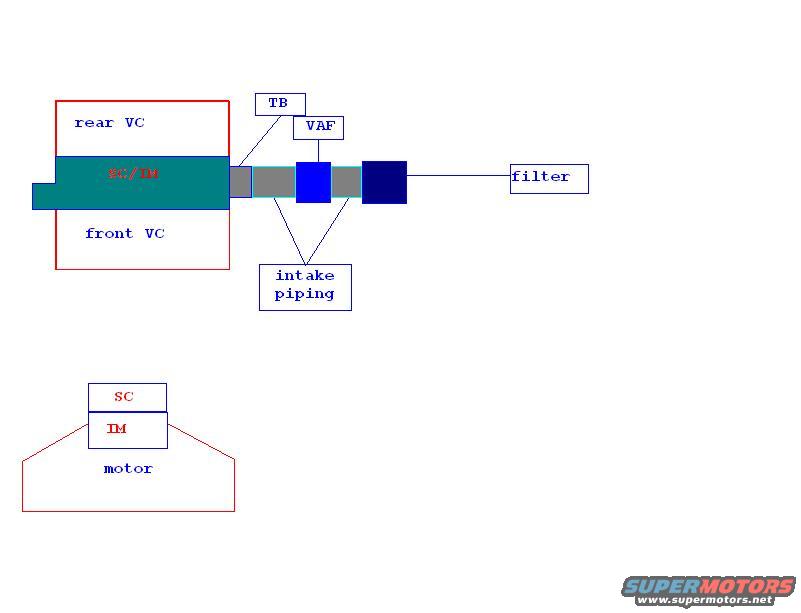
Ford Probe Supercharger Intake Layout Schematic - SC/IM, TB, VAF, Filter Diagram
Reference · 1993-1997 ProbeAll 25 schematics






Block-diagram schematic of an intake air path showing throttle body, VAF, intake piping, filter and supercharger.
Part of 1993-1997 Ford Probe Schematics
This is a simple hand-drawn digital schematic (appears to be created in a basic paint program) illustrating an engine intake layout, apparently for a supercharger/intake manifold arrangement. The upper portion shows a top-down (plan) view: a rectangle labeled 'rear VC' (valve cover) and 'front VC' with a teal bar between them labeled 'SC/IM' (supercharger/intake manifold). Extending to the right of the SC/IM is a series of intake components: gray sections labeled 'intake piping', a blue block labeled with callouts 'TB' (throttle body) and 'VAF' (vane air flow meter), a dark blue block, and a line leading to a box labeled 'filter'. The lower portion shows a side/front view of the engine: a trapezoid shape labeled 'motor' with stacked boxes on top labeled 'IM' (intake manifold) and 'SC' (supercharger). The diagram conveys the ordering of intake components from air filter through VAF meter and throttle body via intake piping into the supercharger/intake manifold mounted atop the engine between the valve covers. No part numbers, dimensions, torque values, or vehicle year/model information appear on the document itself.
Is this accurate? Sign in to help verify it.
Frequently asked questions
- What components are shown in this intake schematic?
- The diagram labels the rear VC (valve cover), front VC, SC/IM (supercharger/intake manifold), TB (throttle body), VAF (vane air flow meter), intake piping, an air filter, and the motor with SC and IM stacked on top.
- Where is the supercharger positioned in this layout?
- The SC/IM unit sits between the rear VC and front VC in the top view, and in the lower view the SC is shown mounted above the IM, which sits on top of the motor.
- What is the order of intake components in this diagram?
- Air flows from the filter through intake piping, past the VAF and TB (throttle body), then through more intake piping into the SC/IM on the engine.
- Does this document specify a vehicle year, engine, or part numbers?
- No. The schematic contains only component labels (VC, SC/IM, TB, VAF, intake piping, filter, motor) and no year, model, engine code, or part numbers.






No comments yet.