MSD 6A/6AL Wiring Diagram - 1996 Mazda KL V6 (Ford Probe GT) Failed OEM Ignitor
Reference · 1993-1997 ProbeAll 65 wiring diagrams
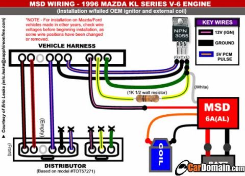

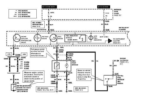
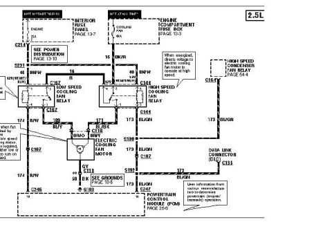
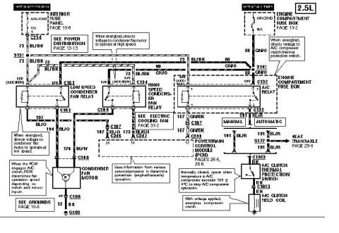
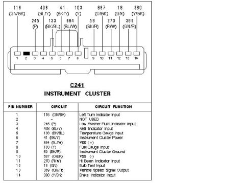





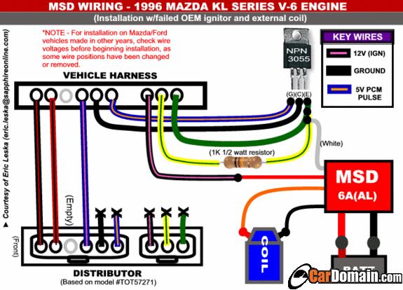
MSD 6A ignition wiring diagram for a 1996 Mazda KL V6 showing color-coded key wires, coil, distributor and resistor.
Part of 1993-1997 Ford Probe Wiring Diagrams
This is a color wiring diagram showing how to install an MSD 6A/6AL ignition box on a 1996 Mazda KL-series V-6 engine when the OEM ignitor has failed, using an external coil. The diagram, credited to Eric Leska ([email protected]), maps the vehicle harness connector wires to the distributor connectors (distributor based on model #TOT57271), an NPN 3055 transistor (with G, C, E pins), a 1K 1/2-watt resistor, the MSD 6A(AL) box, an external coil, and the battery. A key-wires legend identifies the 12V ignition wire, ground wires, and the 5V PCM pulse wire by color. A note warns that on Mazda/Ford vehicles from other years, installers should check wire voltages before starting, since some wire positions may have been changed or removed. One distributor connector position is marked empty, and several wires are shown terminated/unused (marked with X). A reader can learn the overall wiring path from the factory harness through the transistor/resistor trigger circuit into the MSD box and coil, though individual wire colors are conveyed graphically rather than as text.
Is this accurate? Sign in to help verify it.
Frequently asked questions
- What engine does this MSD wiring diagram cover?
- The 1996 Mazda KL series V-6 engine, for installation with a failed OEM ignitor and an external coil.
- Can this diagram be used on other model years of Mazda/Ford vehicles?
- The diagram notes that for Mazda/Ford vehicles made in other years you should check wire voltages before beginning installation, as some wire positions have been changed or removed.
- What extra components are required besides the MSD box?
- An NPN 3055 transistor (pins G, C, E), a 1K 1/2-watt resistor, and an external coil are shown in the diagram.
- What do the key wire colors in the legend mean?
- The legend identifies three key wires: 12V (IGN), GROUND, and a 5V PCM PULSE wire.
- What distributor is the diagram based on?
- The distributor drawing is based on model #TOT57271.






No comments yet.