1993 Ford Probe PCM Connector Pin Chart (Part 2, M/T) - Pinout & Wire Colors
Reference · 1993-1997 ProbeAll 65 wiring diagrams
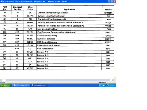
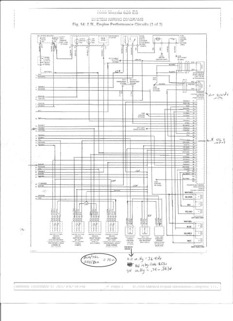
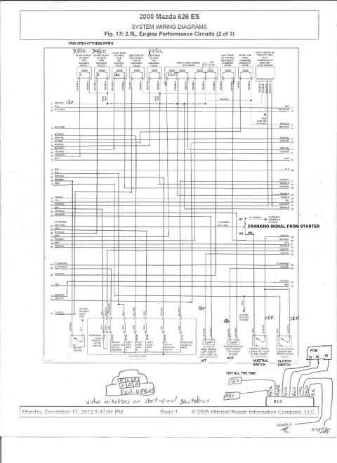
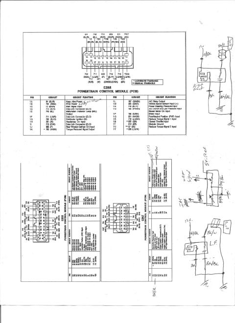
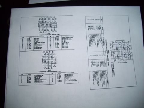
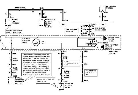
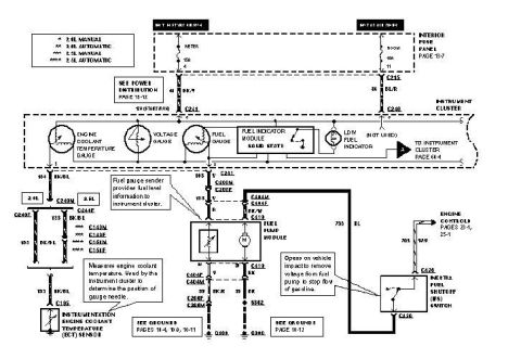
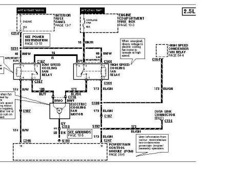
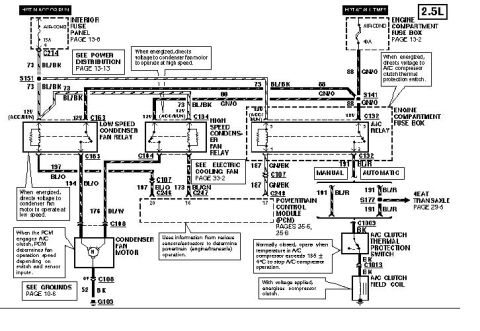
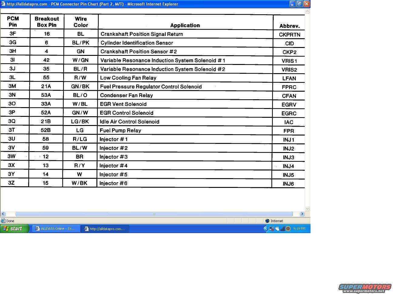
AllData PCM connector pinout (manual-trans, part 2) mapping pins 3F-3Z to crankshaft/CID sensors, VRIS solenoids, cooling-fan relays, EGR solenoids, IAC, fuel pump relay, and injectors 1-6 with wire colors.
Part of 1993-1997 Ford Probe Wiring Diagrams
This document is a screenshot of an ALLDATA Pro page titled 'PCM Connector Pin Chart (Part 2, M/T)', showing a Powertrain Control Module (PCM) connector pinout table for a manual-transmission application. It is filed under a 1993 Ford Probe. The table lists 18 rows covering PCM pins 3F through 3Z, with each row giving the PCM pin ID, the corresponding breakout box pin number, the wire color code, the circuit application, and its abbreviation. Circuits documented include the Crankshaft Position Signal Return (CKPRTN), Cylinder Identification Sensor (CID), Crankshaft Position Sensor #2 (CKP2), Variable Resonance Induction System solenoids #1 and #2 (VRIS1/VRIS2), Low Cooling Fan Relay (LFAN), Fuel Pressure Regulator Control Solenoid (FPRC), Condenser Fan Relay (CFAN), EGR Vent and Control Solenoids (EGRV/EGRC), Idle Air Control Solenoid (IAC), Fuel Pump Relay (FPR), and six fuel injectors (INJ1-INJ6). Wire colors such as BL, BL/PK, GN, W/GN, R/W, GN/BK, LG/BK, R/LG, and W/BK are specified for each circuit. A technician can use this chart to identify PCM connector 3 pin assignments, trace wiring by color, and correlate breakout box pins for diagnostic testing of the engine management system.
Is this accurate? Sign in to help verify it.
Frequently asked questions
- Which PCM pin controls the fuel pump relay on the 1993 Probe (M/T)?
- PCM pin 3T (breakout box pin 52B), with a light green (LG) wire, is the Fuel Pump Relay (FPR) circuit.
- What are the PCM pins for the six fuel injectors?
- Injector #1 is pin 3U (R/LG), #2 is 3V (BL/W), #3 is 3W (BR), #4 is 3X (R/Y), #5 is 3Y (W), and #6 is 3Z (W/BK).
- Which pins control the Variable Resonance Induction System (VRIS) solenoids?
- VRIS Solenoid #1 is PCM pin 3I (breakout box pin 42, W/GN wire) and VRIS Solenoid #2 is pin 3J (breakout box pin 35, BL/R wire).
- What wire color is the Cylinder Identification Sensor (CID) circuit?
- The CID sensor is on PCM pin 3G (breakout box pin 6) with a blue/pink (BL/PK) wire.
- Which PCM pins operate the EGR solenoids?
- The EGR Vent Solenoid (EGRV) is pin 3O (33A, W/BL) and the EGR Control Solenoid (EGRC) is pin 3P (52A, GN/W).



No comments yet.