1993 Ford Probe Ignition System Schematic - Distributor, ICM & PCM Wiring
Reference · 1993-1997 ProbeAll 25 schematics





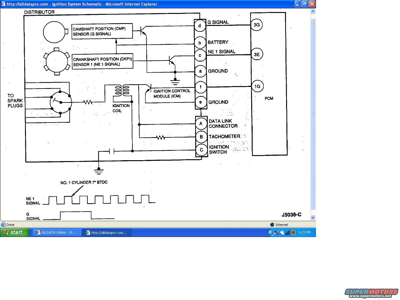
Ignition system schematic showing camshaft/crankshaft position sensors, ignition coil, control module and PCM with NE1 and G signal waveforms.
Part of 1993-1997 Ford Probe Schematics
This document is a screenshot of an ALLDATA (alldatapro.com) ignition system schematic, uploaded as a reference for a 1993 Ford Probe. The diagram shows the internal layout of the distributor assembly, which houses the Camshaft Position (CMP) sensor providing the G signal, the Crankshaft Position (CKP1) sensor providing the NE 1 signal, the ignition coil (with output to the spark plugs via the rotor/cap), and the Ignition Control Module (ICM). The distributor connector pins are labeled: d (G signal to PCM pin 3G), b (battery), c (NE 1 signal to PCM pin 3E), a (ground), f (to PCM pin 1G), and e (ground). A second connector routes pin A to the data link connector, pin B to the tachometer (through a resistor), and pin C to the ignition switch. At the bottom, timing waveforms are illustrated: the NE 1 signal is a repeating square wave, with one pulse edge marked as No. 1 cylinder at 7° BTDC, and the G signal appears as a single wider pulse per cycle. Diagram reference number J5038-C appears at the lower right. A reader can learn distributor pinouts, PCM signal connections, and ignition signal timing relationships from this schematic.
Is this accurate? Sign in to help verify it.
Frequently asked questions
- What sensors are located inside the distributor on this schematic?
- The Camshaft Position (CMP) sensor, which produces the G signal, and Crankshaft Position (CKP1) Sensor 1, which produces the NE 1 signal. The ignition coil and Ignition Control Module (ICM) are also shown inside the distributor assembly.
- Which PCM pins receive the distributor signals?
- The G signal goes to PCM pin 3G, the NE 1 signal goes to PCM pin 3E, and connector pin f connects to PCM pin 1G.
- What are the distributor connector pin assignments?
- Pin d = G signal, pin b = battery, pin c = NE 1 signal, pins a and e = ground, pin f = to PCM (1G). A second connector has pin A = data link connector, pin B = tachometer, and pin C = ignition switch.
- What timing reference is shown for the NE 1 signal?
- The waveform diagram marks a pulse on the NE 1 signal as No. 1 cylinder at 7° BTDC.
- Where does the tachometer signal come from in this diagram?
- The tachometer connects through pin B of the lower connector, via a resistor, to the ignition circuit inside the distributor.






No comments yet.