1996 Ford Probe 2.5L PCM Connector C247 Pinout - Wire Colors & Functions

Reference · 1993-1997 ProbeAll 65 wiring diagrams
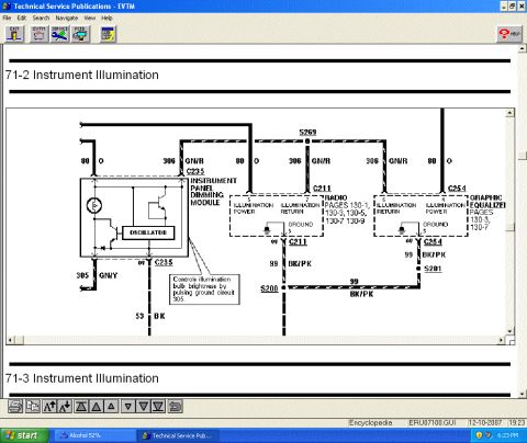
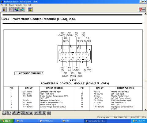

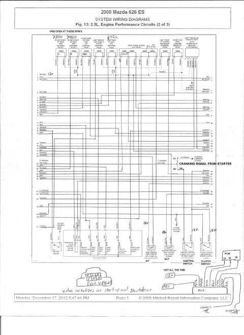
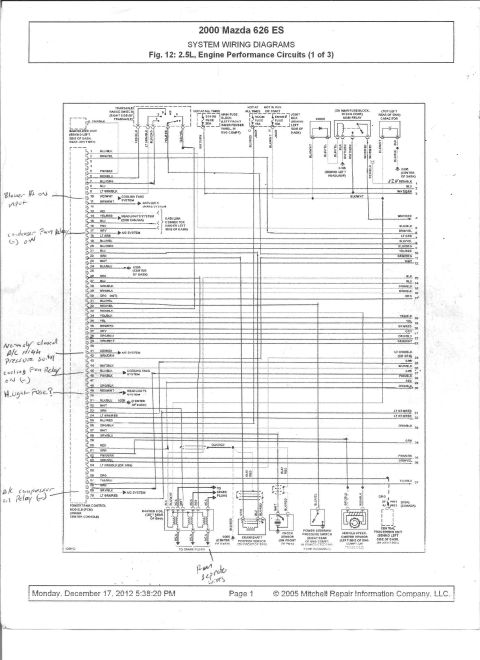
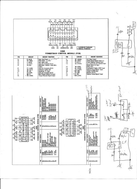
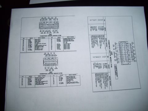
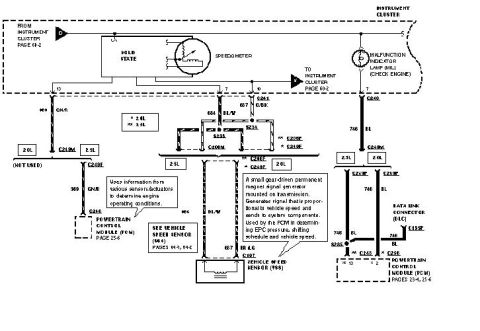
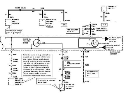
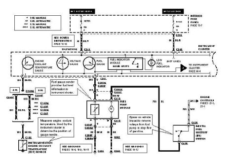
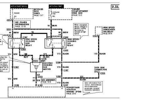
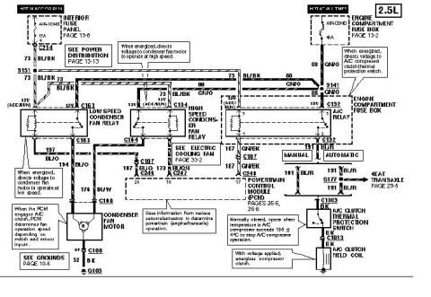





Powertrain Control Module (PCM) connector C247 pinout with color-coded circuits and a pin function table for the 2.5L.
Part of 1993-1997 Ford Probe Wiring Diagrams
This document is a screenshot from Ford's EVTM (Electrical and Vacuum Troubleshooting Manual) Technical Service Publications software showing connector C247, the Powertrain Control Module (PCM) connector for the 2.5L engine. It includes a pin-face illustration of the 16-pin connector (pins 1-8 top row, 9-16 bottom row) with circuit numbers and wire color codes called out for each terminal, plus a legend table listing every pin, its circuit number, wire color, and circuit function. Circuit functions include Barometric Pressure Input (pin 1, circuit 837 GN/O, automatic transaxle only), Right and Left HO2S inputs, Engine Coolant Temperature, Reference Voltage Output, Intake Air Temperature, Knock Sensor Input, Canister Purge Solenoid Output, Volume Air Flow Input, Throttle Position Input, A/C High Pressure Input, EGR Valve Position Input, DRL Module Input, and High Speed Condenser Fan Control. Pins 4 and 15 are marked NOT USED. A footnote indicates the asterisked circuit (837) applies to automatic transaxle applications. The taskbar shows the source disc labeled 96CAR06_0, suggesting a 1996 model-year car EVTM. This is a useful reference for diagnosing PCM sensor circuits, verifying wire colors, and pin-testing the C247 connector on 2.5L-equipped vehicles.
Is this accurate? Sign in to help verify it.
Frequently asked questions
- What is connector C247 on the 2.5L engine?
- C247 is a 16-pin Powertrain Control Module (PCM) connector, applicable to the 2.5L engine only, with pins 1-8 on the top row and 9-16 on the bottom row.
- Which pin is the Throttle Position input on the C247 PCM connector?
- Pin 11, circuit 815 with a yellow (Y) wire, is the Throttle Position Input.
- Which pins of C247 are not used?
- Pins 4 and 15 are marked NOT USED.
- What wire colors are used for the oxygen sensor inputs?
- Right HO2S Input is pin 2, circuit 720 (BK/Y); Left HO2S Input is pin 10, circuit 726 (BL/W).
- What does the asterisk on circuit 837 mean?
- The asterisk indicates the circuit applies to the automatic transaxle; circuit 837 (GN/O) at pin 1 is the Barometric Pressure Input.






No comments yet.