Ford Probe Instrument Illumination Wiring Diagram 71-2 - Dimmer, Radio, EQ
Reference · 1993-1997 ProbeAll 65 wiring diagrams
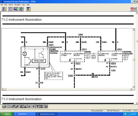

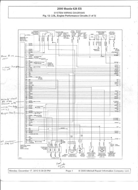
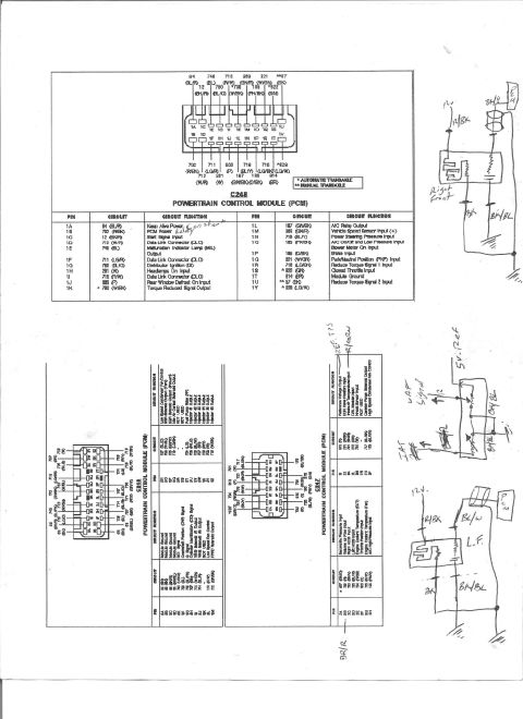
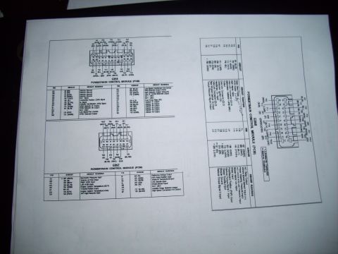
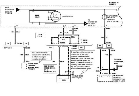
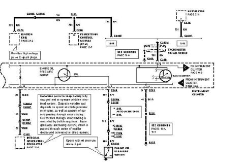
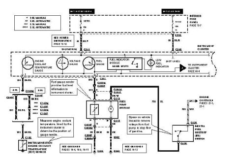
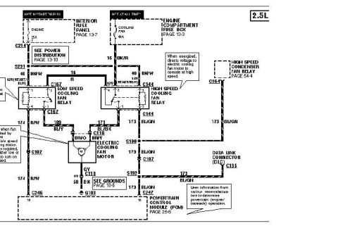
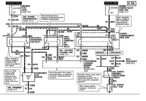





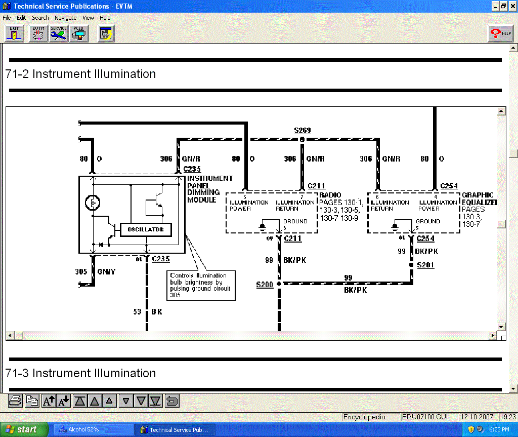
Wiring diagram of the instrument illumination circuit showing the dimming module, radio/equalizer feeds and color-coded wires.
Part of 1993-1997 Ford Probe Wiring Diagrams
This is a screenshot from Ford's Technical Service Publications EVTM (Electrical and Vacuum Troubleshooting Manual) software showing wiring diagram section 71-2, Instrument Illumination. The diagram illustrates the instrument panel dimming module (connector C235), the radio (connector C211, referenced on pages 130-1, 130-3, 130-5, 130-7, 130-9), and the graphic equalizer (connector C254, referenced on pages 130-3 and 130-7). Illumination power is delivered on circuit 80 (orange wire) and illumination return on circuit 306 (green/red wire), joined at splice S269. The dimming module contains an oscillator and, per the diagram callout, controls illumination bulb brightness by pulsing ground circuit 305 (green/yellow wire); its ground is circuit 53 (black). The radio uses pin 5 for illumination power and pin 7 for illumination return; the equalizer uses pin 4 for power and pin 6 for return. Both components ground through circuit 99 (black/pink) to splices S200 and S201. The file reference shown is ERU07100.GUI. A reader can learn the wire colors, circuit numbers, connector pin assignments, and splice locations needed to diagnose instrument, radio, and equalizer illumination/dimming problems.
Is this accurate? Sign in to help verify it.
Frequently asked questions
- How does the instrument panel dimming module control brightness?
- Per the diagram callout, it controls illumination bulb brightness by pulsing ground circuit 305 (GN/Y wire) using an internal oscillator.
- What wire colors carry illumination power and return?
- Circuit 80 is orange (O) for illumination power and circuit 306 is green/red (GN/R) for illumination return, joined at splice S269.
- Which radio connector pins are used for illumination?
- At connector C211, pin 5 is illumination power and pin 7 is illumination return. The radio circuits are shown on pages 130-1, 130-3, 130-5, 130-7 and 130-9.
- What pins does the graphic equalizer use for illumination?
- At connector C254, pin 4 is illumination power and pin 6 is illumination return, with ground through circuit 99 BK/PK via splice S201 to S200.
- What is the ground circuit for the dimming module?
- The instrument panel dimming module grounds through circuit 53, a black (BK) wire, from connector C235.






No comments yet.